
Project Overview
In circuit 1B, you got to use a potentiometer, which varies resistance based on the twisting of a knob. In this circuit you’ll be using a photoresistor, which changes resistance based on how much light the sensor receives. Using this sensor you can make a simple night-light that turns on when the room gets dark and turns off when it is bright.
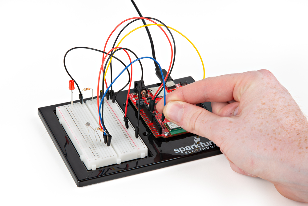
Project 1 - Circuit C

New Components
Photoresistor
Photoresistors, or photocells, are light-sensitive, variable resistors. As more light shines on the sensor’s head, the resistance between its two terminals decreases. They’re an easy-to-use component in projects that require ambient-light sensing.

New Concepts
Analog to Digital Conversion
The world we live in is analog, but the RedBoard lives in a digital world. In order to have the RedBoard sense analog signals, we must first pass them through an Analog to Digital Converter (or ADC). The six analog inputs (A0–A5) covered in the last circuit all use an ADC. These pins “sample” the analog signal and create a digital signal for the microcontroller to interpret. The “resolution” of this signal is based on the resolution of the ADC. In the case of the RedBoard, that resolution is 16-bit. With a 16-bit ADC, we get 2 ^ 16 = 65536 possible values, which is why the analog signal varies between 0 and 65535.
Voltage Divider Continued
Since the RedBoard can’t directly interpret resistance (rather, it reads voltage), we need to use a voltage divider to use our photoresistor, a part that doesn’t output voltage. The resistance of the photoresistor changes as it gets darker or lighter. That changes the amount of voltage that is read on the analog pin, which “divides” the voltage, 3.3V in this case. That divided voltage is then read on the analog to digital converter.
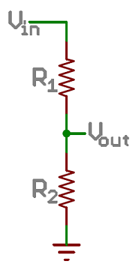
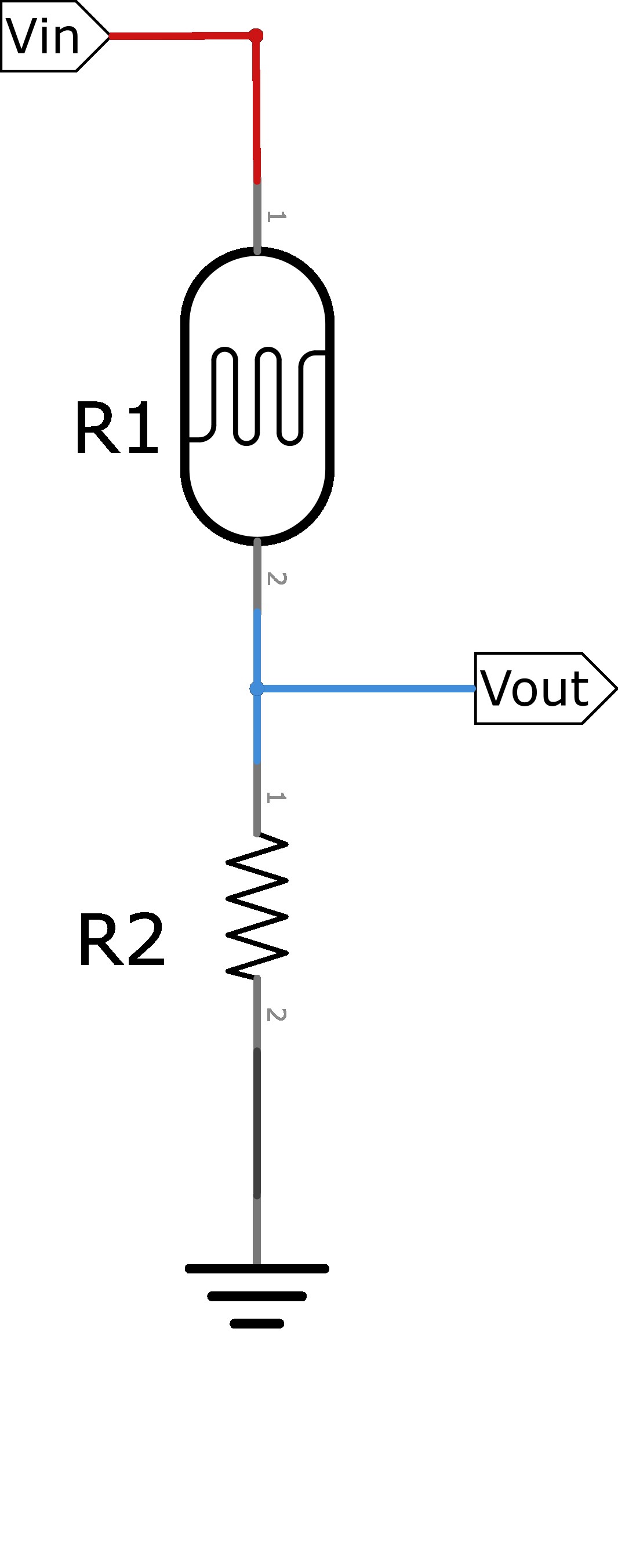
Top: A regular voltage divider circuit. Vout will be a constant voltage. Bottom: A variable voltage divider circuit. Vout will fluctuate as the resistance of the photoresistor changes.
The voltage divider equation assumes that you know three values of the above circuit: the input voltage (Vin), and both resistor values (R1 and R2). Given those values, we can use this equation to find the output voltage (Vout):

If R2 is a constant value (the resistor) and R1 fluctuates (the photoresistor), the amount of voltage measured on the Vout pin will also fluctuate.
Hookup Guide
Note that the photoresistor is not polarized. It can be inserted in either direction.
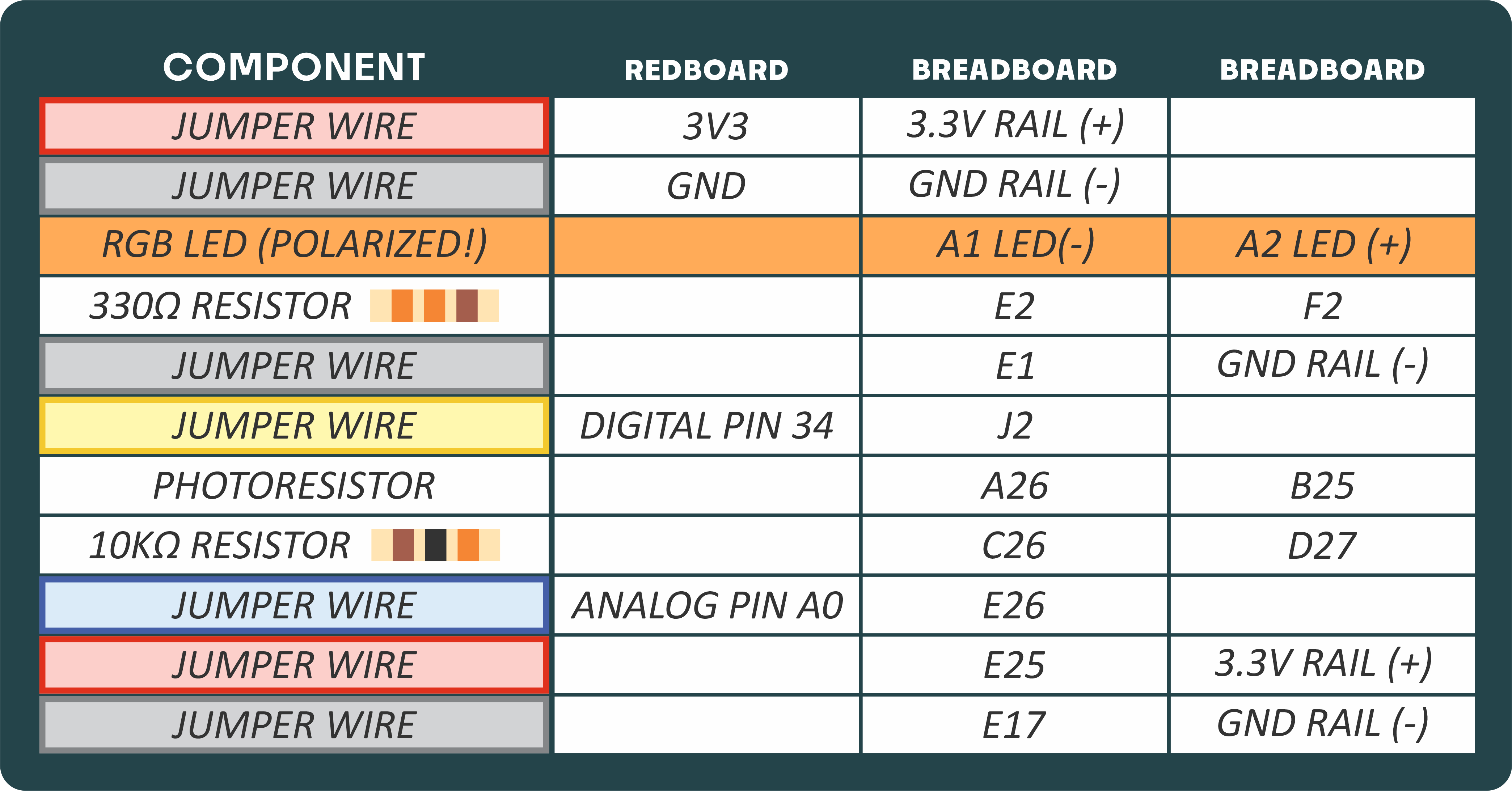
READY TO START HOOKING EVERYTHING UP? Check out the circuit diagram and hookup table below to see how everything is connected.
Circuit Diagram
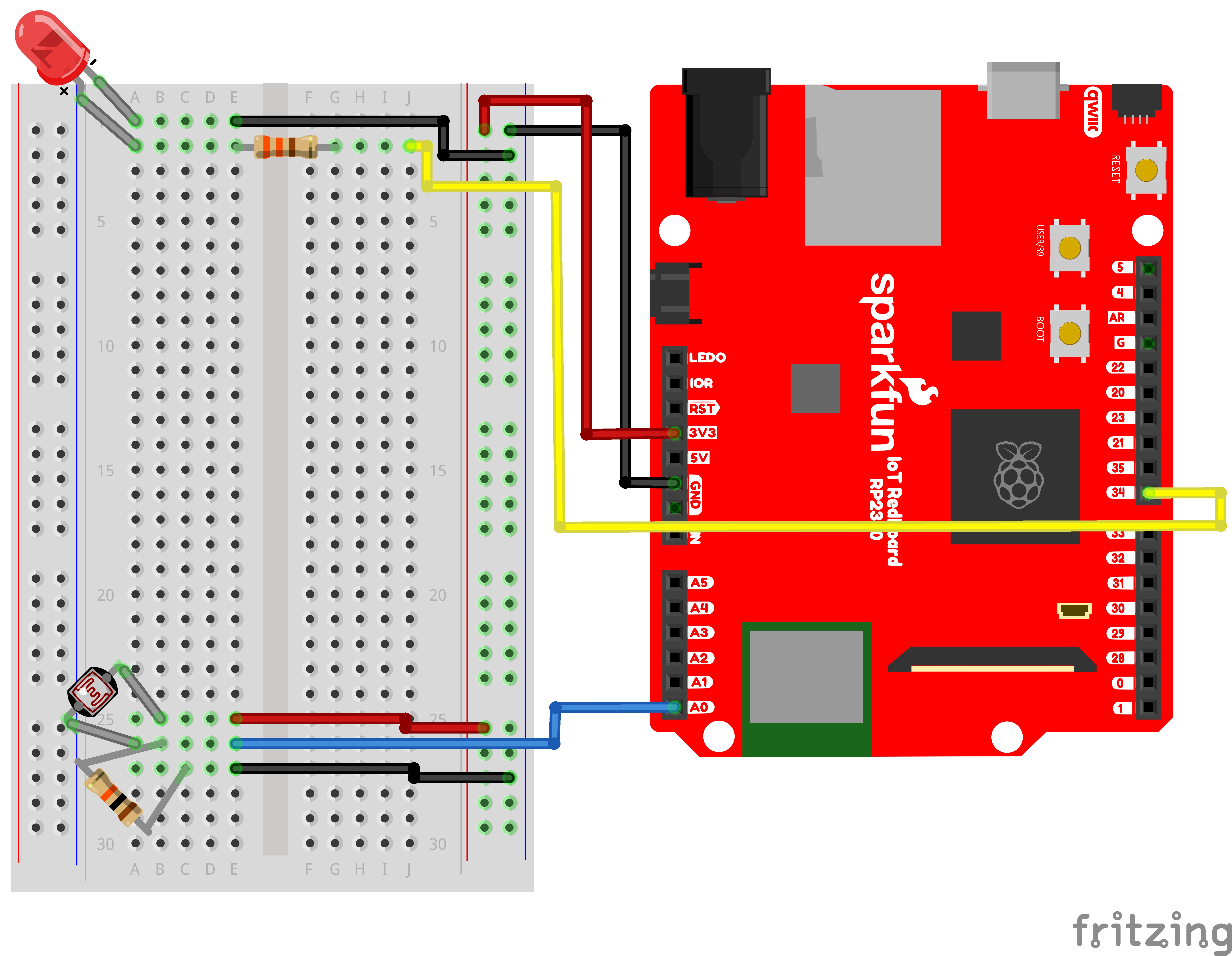
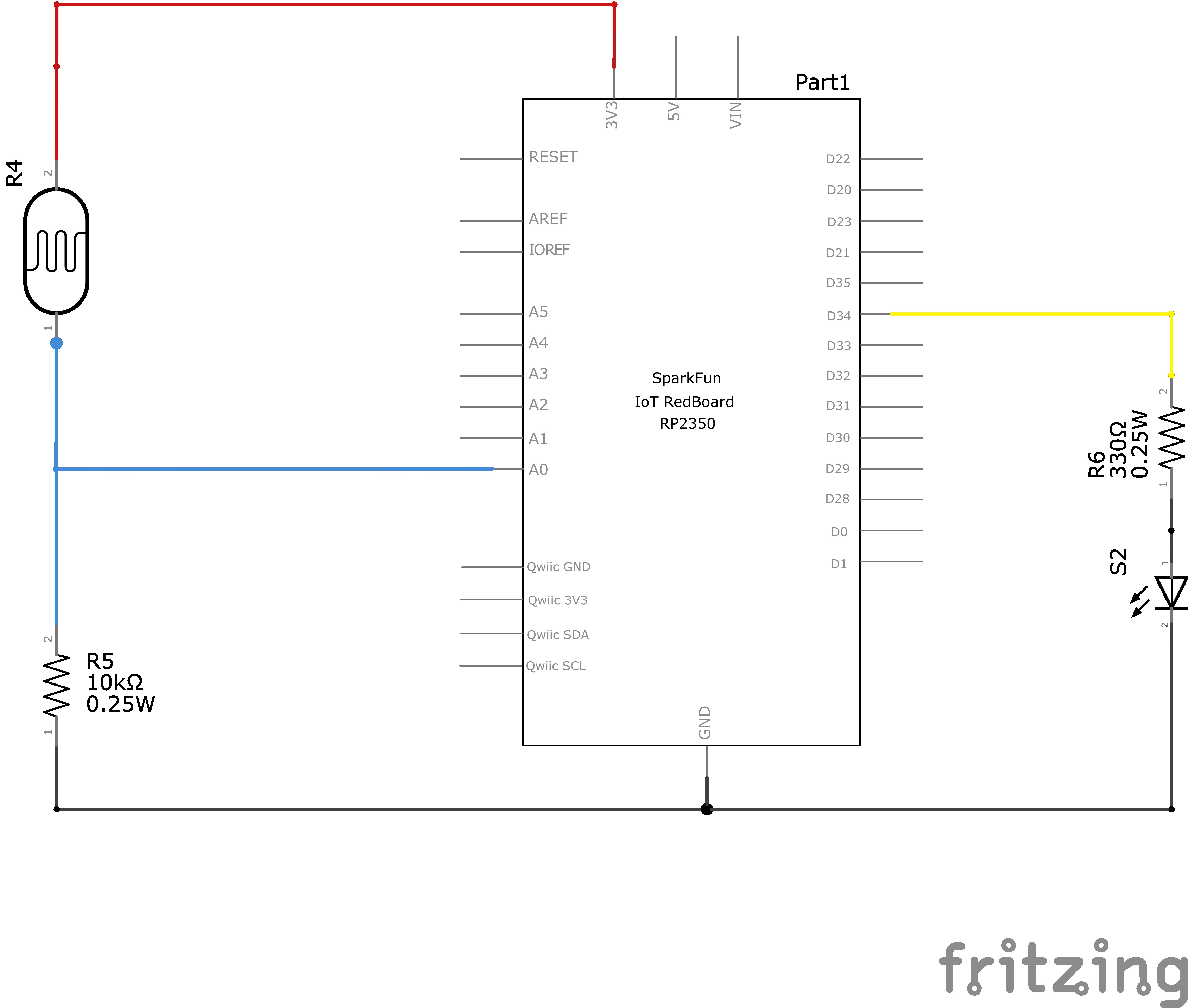
Note for Advanced Users: If you know how to read datasheets and schematics, you can also refer to the schematic below as an alternative.
Hookup Table
Programming the RedBoard
The SparkFun RedBoard IoT is programmed using MicroPython and this project uses MicroPython commands to control the circuit. Before this is possible, a MicroPython tool is needed to communicate with the RedBoard.
Selecting a MicroPython Tool
Our suggested tool is the Thonny IDE. For instructions on how to install and use Thonny, check out our Thonny Guide.
The first step to enter commands on the RedBoard is to select a tool that allows direct interaction with MicroPython.
While a variety of methods exist to communicate with the RedBoard, the following tools are the most popular: Thonny, PyCharm and the command mpremote.
Once you select and install a tool, make sure your RedBoard is connected to your computer, and the micropython tool is connected to the RedBoard. Once connected, you should have access to the MicroPython REPL command line.
Remember that the source files for each SIK circuit are already on your IoT RedBoard RP2350 in the “sik_examples” folder. So if using the suggested Thonny tool, you can select the example for this circuit and run it directly with the green “run current script” button rather than executing lines individually.
Entering MicroPython Commands
Step 1 - Setup
Like last circuit, to operate the LED, we need to enable the board pin 34 (the pin that the LED is connected to in the circuit).
To do this we load the Pin definition for the board
from machine import PinNext, we load the ADC object to allow us to read our analog pin
from machine import ADCNow we declare our digital pin for the led and our “ADC” to read the analog pin for the photoresistor
led_pin = Pin(34, Pin.OUT) # Create a pin variable for the led pin (pin 34)
photoresistor = ADC(Pin.board.A0) # Create an ADC variable for reading the photoresistor value from analog pin A0
Now, we can read from A0 to read the photoresistor value:
print(photoresistor.read_u16()) # Use the read_u16 method to read the value of our photoresistor.Now let’s create an infinite loop and turn on the LED when the photoresistor reads under a certain value and turn it off when it reads over a certain value. That way it can act as a night light.
# Now, let's turn the LED on and off based on the photoresistor value.
import time # Allows us to use "time.sleep()" to delay for a certain number of seconds

# We'll set our threshold to half of the maximum value of the ADC reading (65535)
threshold = 65535 / 2

# Infinite loop so this cell keeps running until we stop it.
while True:
    photoValue = photoresistor.read_u16() # Get the new photoresistor value (0 - 65535)

    print(f"Photoresistor Value: {photoValue : 5}", end='\r') # Print our Photoresistor reading (don't mind the fanciness of this line it just makes the print format nicely)

    # Turn on the LED but only if the photoresistor value is below the threshold
    if photoValue < threshold:
        led_pin.high()
    else:
        led_pin.low()

    # A short delay to make the printout easier to read
    time.sleep(0.250)
What You Should See
The program stores the light level in a variable. Then, using an if/else statement, the program checks to see what it should do with the LED. If the variable is above the threshold (it’s bright), turn the LED off. If the variable is below the threshold (it’s dark), turn the LED on. You now have just built your own night-light!
Coding Challenges
| Challenge | Description |
|---|---|
| Response Pattern | Right now your if statement turns the LED on when it gets dark, but you can also use the light sensor like a no-touch button. Try using low(), high() and sleep() to make the LED blink a pattern when the light level drops, then calibrate the threshold variable in the code so that the blink pattern triggers when you wave your hand over the sensor. |
| Replace Photoresistor's 330Ω Resistor with LED. | Alter the circuit by replacing the 330Ω resistor with an LED (the negative leg should connect to GND). Now what happens when you place your finger over the photoresistor? This is a great way to see Ohm's law in action by visualizing the change in resistance's effect on the current flowing through the LED. |
Troubleshooting
| Problem | Solution |
|---|---|
| The light never turns on or always stays on | Look at the value that the photoresistor is reading in a bright room (e.g., 915). Cover the photoresistor, or turn the lights off. Then look at the new value that the photoresistor is reading (e.g., 550). Set the threshold in between these two numbers (e.g., 700) so that the reading is above the threshold when the lights are on and below the threshold when the lights are off. |
| Nothing is printing. | Ensure you are connected to the correct serial port and have run the correct code example (or properly copied and pasted all code blocks from this guide in-order). |
You’ve Completed Circuit 1C!
Continue to circuit 1D to learn about RGB LEDs