
Project Overview
Get ready to learn about digital inputs and buttons as you build your own digital trumpet!
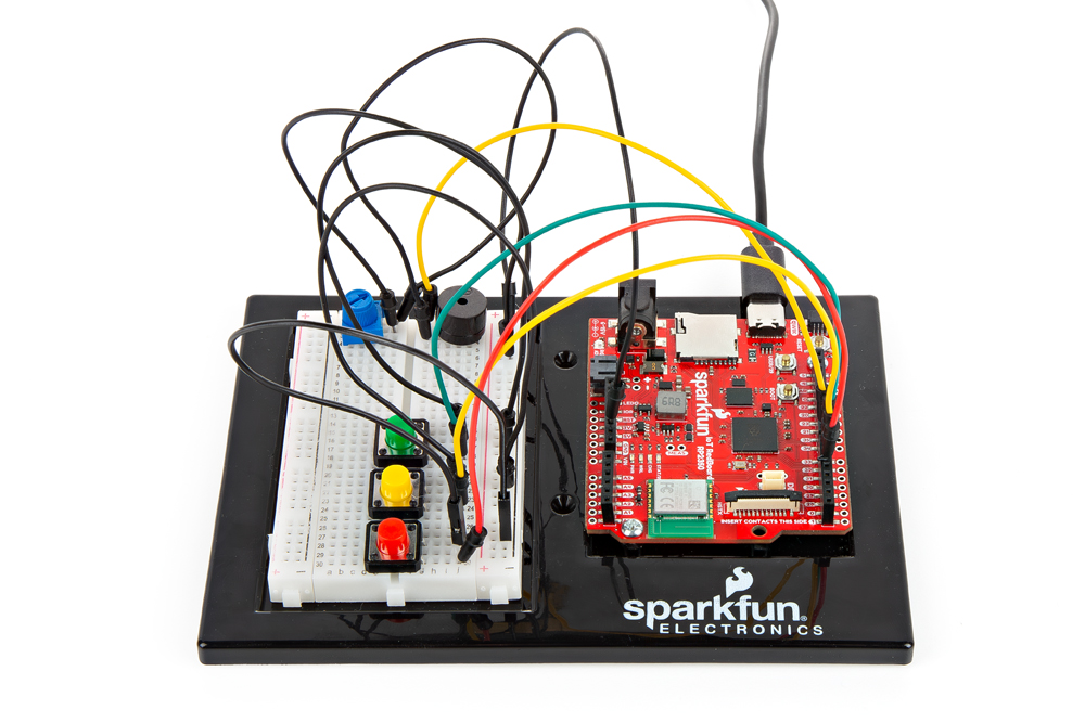
Project 2 - Circuit B

New Components
Buttons
Buttons, also known as momentary switches, are switches that only remain in their on state as long as they’re being actuated, or pressed. Most often momentary switches are best used for intermittent user-input cases: reset button and keypad buttons. These switches have a nice, tactile, “clicky” feedback when you press them.
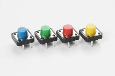
All of the buttons included behave the same no matter their color.
New Concepts
Binary Number System
Number systems are the methods we use to represent numbers. We’ve all been mostly operating within the comfy confines of a base-10 number system, but there are many others. The base-2 system, otherwise known as binary, is common when dealing with computers and electronics. There are really only two ways to represent the state of anything: ON or OFF, HIGH or LOW, 1 or 0. And so, almost all electronics rely on a base-2 number system to store and manipulate numbers. The heavy reliance electronics places on binary numbers means it’s important to know how the base-2 number system works.
Digital Input
In circuit 1A, you worked with digital outputs. This circuit focuses on digital inputs. Digital inputs only care if something is in one of two states: TRUE or FALSE, HIGH or LOW, ON or OFF. Digital inputs are great for determining if a button has been pressed or if a switch has been flipped.
Pull-up Resistors
A pull-up resistor is a small circuit that holds the voltage HIGH (3.3V, 5V, etc.) on a pin until a button is pressed, pulling the voltage LOW (0V). The most common place you will see a pull-up resistor is when working with buttons. A pull-up resistor keeps the button in one state until it is pressed. The RedBoard has built-in pull-up resistors, but they can also be added to a circuit externally. This circuit uses the internal pull-up resistors, which you can see comments about in the code cells.
Hookup Guide
Buttons are not polarized. However, they do merit a closer look. Buttons make momentary contact from one connection to another, so why are there four legs on each button? The answer is to provide more stability and support to the buttons in your breadboard circuit. Each row of legs is connected internally. When the button is pressed, one row connects to the other, making a connection between all four pins.
The buzzer is polarized. To see which leg is positive and which is negative, flip the buzzer over and look at the markings underneath. Keep track of which pin is where, as they will be hard to see once inserted into the breadboard. There is also text on the positive side of the buzzer, along with a tiny (+) symbol.
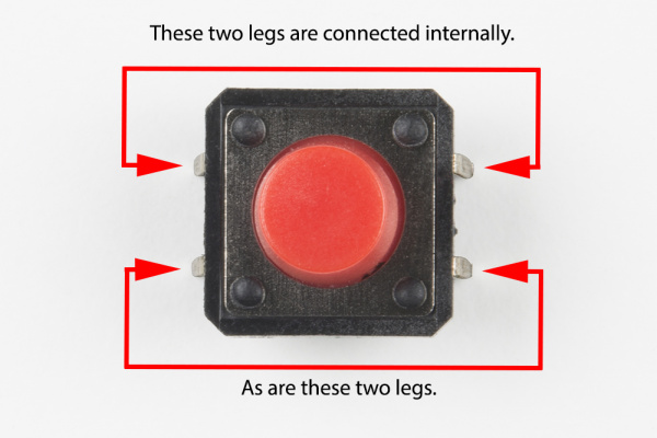
If the button’s legs don’t line up with the slots on the breadboard, rotate it 90 degrees.
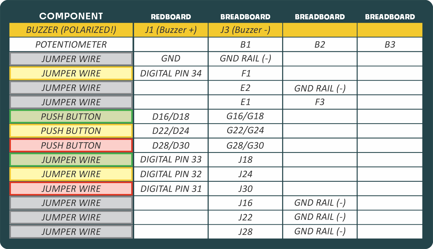
READY TO START HOOKING EVERYTHING UP? Check out the circuit diagram and hookup table below to see how everything is connected.
Circuit Diagram
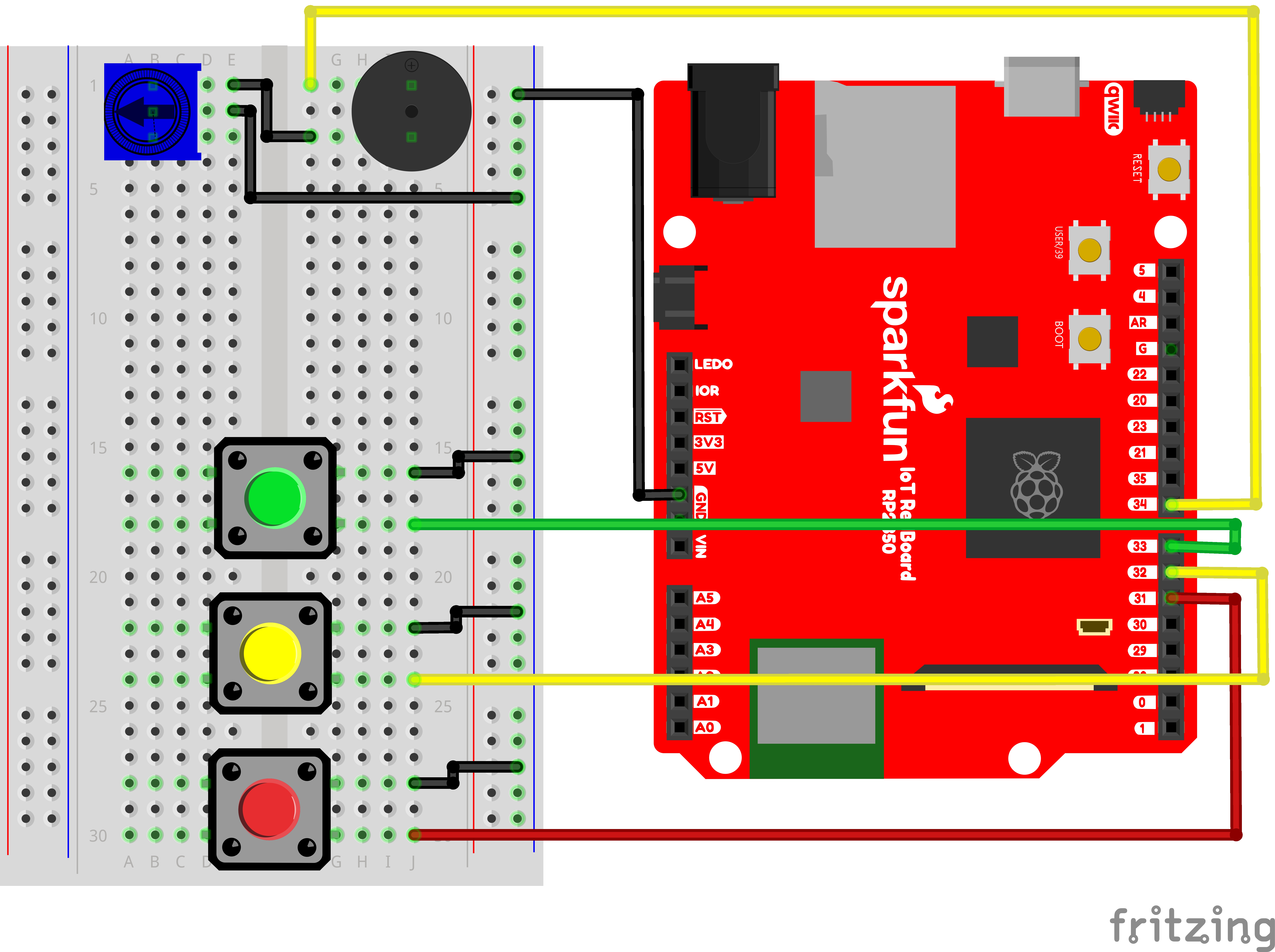
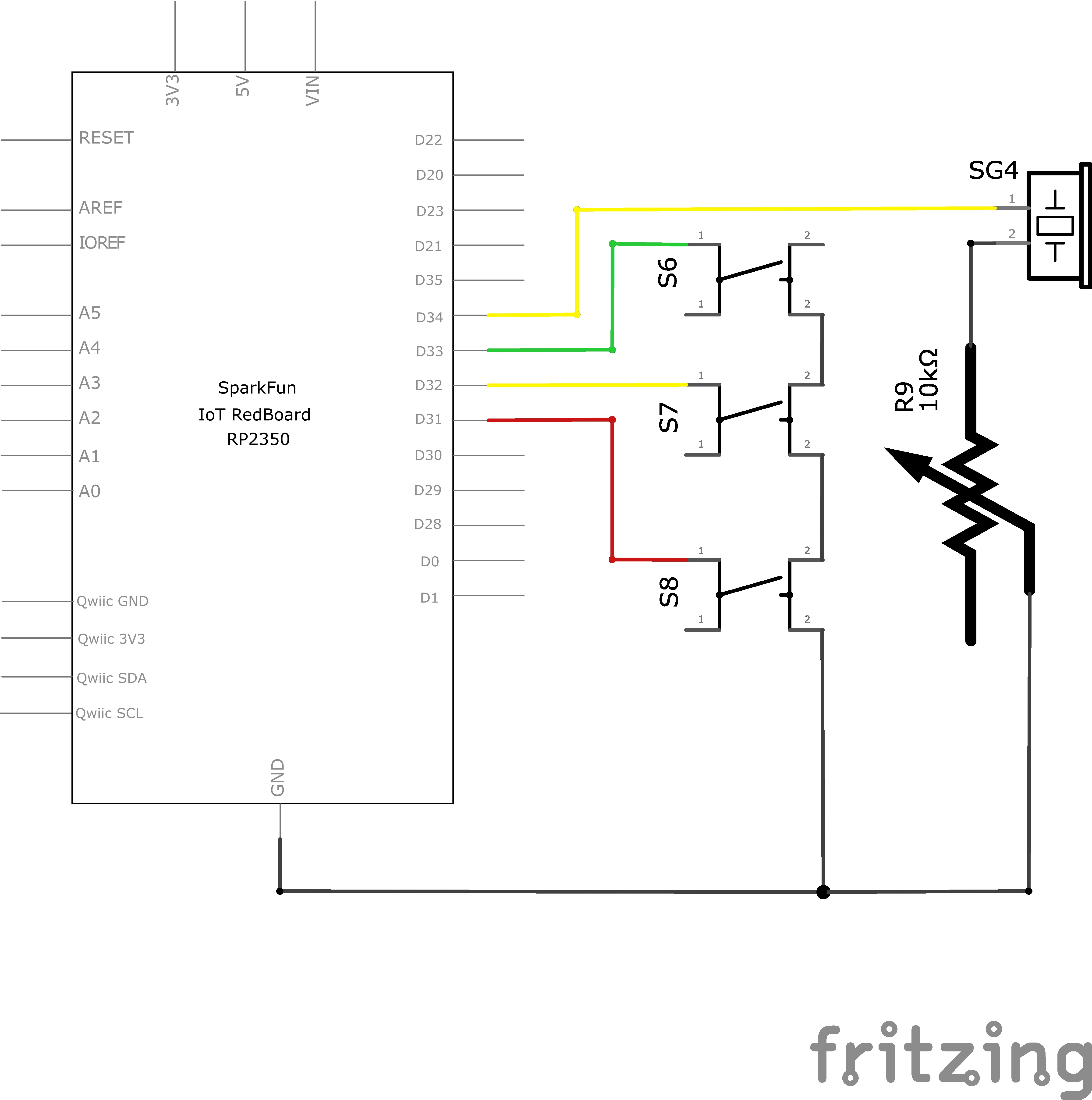
Note for Advanced Users: If you know how to read datasheets and schematics, you can also refer to the schematic below as an alternative.
Hookup Table
Programming the RedBoard
The SparkFun RedBoard IoT is programmed using MicroPython and this project uses MicroPython commands to control the circuit. Before this is possible, a MicroPython tool is needed to communicate with the RedBoard.
Selecting a MicroPython Tool
Our suggested tool is the Thonny IDE. For instructions on how to install and use Thonny, check out our Thonny Guide.
The first step to enter commands on the RedBoard is to select a tool that allows direct interaction with MicroPython.
While a variety of methods exist to communicate with the RedBoard, the following tools are the most popular: Thonny, PyCharm and the command mpremote.
Once you select and install a tool, make sure your RedBoard is connected to your computer, and the micropython tool is connected to the RedBoard. Once connected, you should have access to the MicroPython REPL command line.
Remember that the source files for each SIK circuit are already on your IoT RedBoard RP2350 in the “sik_examples” folder. So if using the suggested Thonny tool, you can select the example for this circuit and run it directly with the green “run current script” button rather than executing lines individually.
Entering MicroPython Commands
Step 1 - Setup
Lets start by importing any of the libaries we plan on using and setting up our pins.
from machine import Pin # Allows us to use "Pin" to use code to interface with the pins on our board
from machine import PWM # Allows us to use "PWM" (pulse-width modulation) to control the brightness of our LED

firstKeyPin = Pin(33, Pin.IN, Pin.PULL_UP) # Create a Pin object for the first key (green) on pin 33, set as input with pull-up resistor
secondKeyPin = Pin(32, Pin.IN, Pin.PULL_UP) # Create a Pin object for the second key(yellow) on pin 32, set as input with pull-up resistor
thirdKeyPin = Pin(31, Pin.IN, Pin.PULL_UP) # Create a Pin object for the third key (red) on pin 35, set as input with pull-up resistor

pwmSpeaker  = PWM(Pin(34), freq=0, duty_u16=0) # Create a PWM object on pin 34 with a frequency of 0Hz and an initial "on time" of 0 (off)
Step 2 - Reading Buttons to Decide Buzzer Frequency
Now for each button, let’s check if the button is pressed or not and play a different note for each!
To read our digital inputs, we’ll check whether they are high (1) or low (0) with their built in value() function.
# In an infinite loop, we will check the state of the keys and play a note when a key is pressed
while True:
    if firstKeyPin.value() == 0: # If the first key is pressed (value is low)
        pwmSpeaker.freq(262) # Play the note C (262Hz)
        pwmSpeaker.duty_u16(32768) # Set the duty cycle to 50% (half as loud as possible)
    elif secondKeyPin.value() == 0: # If the second key is pressed (value is low)
        pwmSpeaker.freq(330) # Play the note E (330Hz)
        pwmSpeaker.duty_u16(32768) # Set the duty cycle to 50% (half as loud as possible)
    elif thirdKeyPin.value() == 0: # If the third key is pressed (value is low)
        pwmSpeaker.freq(392) # Play the note G (392Hz)
        pwmSpeaker.duty_u16(32768) # Set the duty cycle to 50% (half as loud as possible)
    else: # If no key is pressed
        pwmSpeaker.freq(0)
        pwmSpeaker.duty_u16(0) # turn off the speaker

# Frequency Table: Feel free to change the frequencies for each button press to play different notes.
# note  frequency
# c     262 Hz
# d     294 Hz
# e     330 Hz
# f     349 Hz
# g     392 Hz
# a     440 Hz
# b     494 Hz
# C     523 Hz
What You Should See
Different tones will play when you press different keys. Turning the potentiometer will adjust the volume.
Coding Challenges
| Challenge | Description |
|---|---|
| Change the key of each button | Use the frequency table in the comment section at the end of the code to change the notes that each button plays. |
| Play more than three notes with if statements | By using combinations of buttons, you can play up to seven notes of the scale. You can do this in a few ways. To get more practice with if statements, try adding seven if statements and using the Boolean and operator to represent all of the combinations of keys. |
| Play more than three notes with binary math | You can use a clever math equation to play more than three notes with your three keys. By multiplying each key by a different number, then adding up all of these numbers, you can make a math equation that produces a different number for each combination of keys. |
Troubleshooting
| Problem | Solution |
|---|---|
| The buzzer is too loud or too quiet | Turn the potentiometer to adjust the volume. |
| The RedBoard thinks one key is always pressed | Check your wiring. You may have ground and power backward if one or more buttons behave as though they're pressed all the time. |
| The buttons are not working | First, make sure that the wiring is correct. It is easy to misalign a wire with a button leg. Second, make sure that you have declared your buttons as inputs and have enabled the internal pull-up resistors with Pin.IN and Pin.PULL_UP. |
You’ve Completed Circuit 2B!
Continue to circuit 2C to learn about for loops, measuring durations, and put together all you’ve learned in project 2.