SparkFun Inventor's Kit
Assembly Guide
SIK Assembly
Inventory, Baseplate, RedBoard & Breadboard Assembly
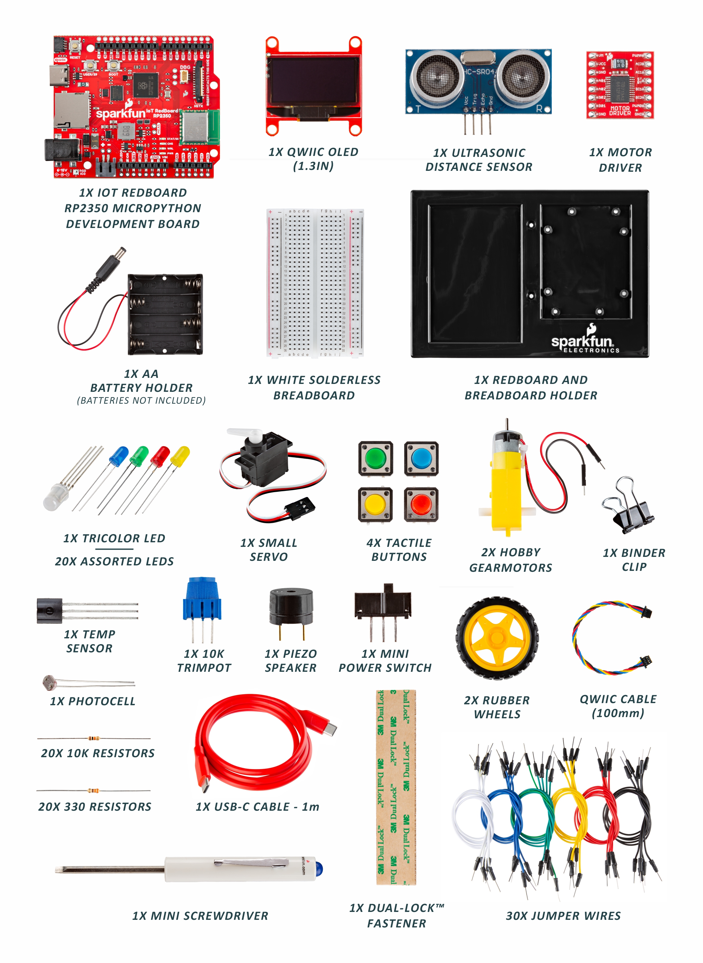
Inventory of Parts
The kit includes common components you’ll use across projects (LEDs, resistors, buttons, sensors, motors, LCD, jumpers, the RedBoard, and a breadboard).
Baseplate Assembly
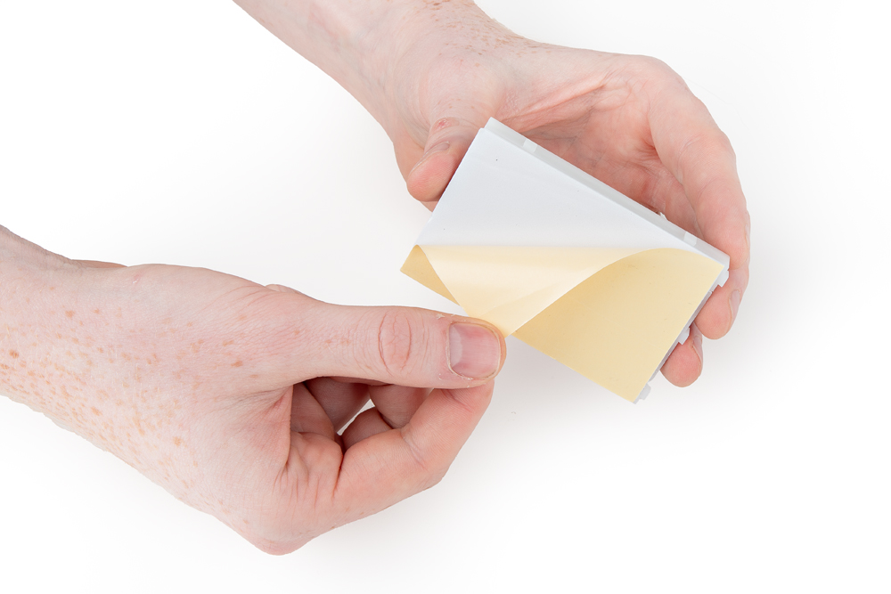
Assemble the base to keep the RedBoard and breadboard together while you build. Gather the RedBoard, breadboard, included screwdriver, baseplate, and two screws. If needed, flip the driver to the Phillips head.
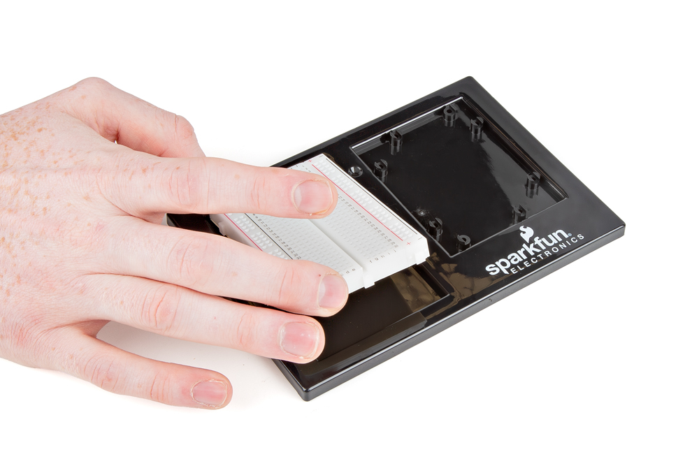
Install the Breadboard
Peel the adhesive, align the breadboard with the outline (text facing the same direction as the baseplate), and press firmly to stick.
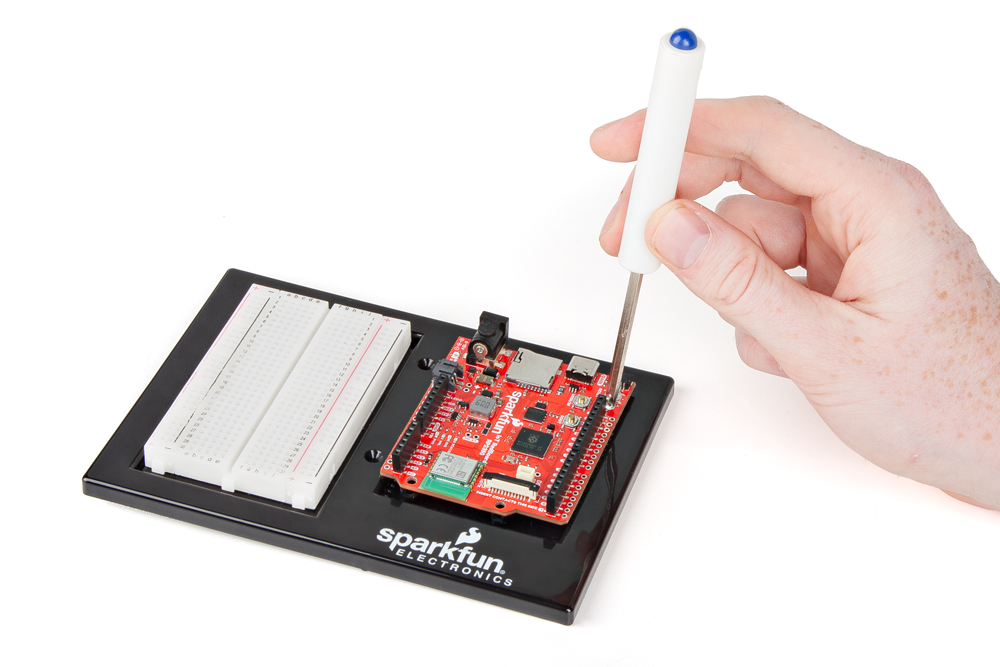
Install the RedBoard
Place the RedBoard in its spot with text oriented the same way. Drive one screw, then the screw diagonally opposite. The plastic standoffs aren’t threaded—apply steady pressure.
Anatomy of the SparkFun RedBoard
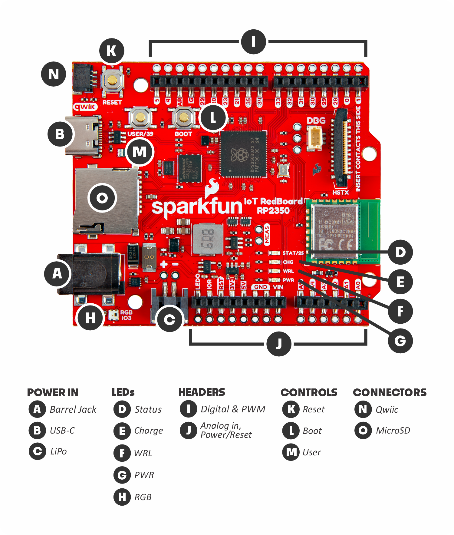
Power In:
- (A) Barrel jack: The barrel jack is used to power the RedBoard from a dedicated power supply like the battery pack included in this kit.
- (B) USB-C: The USB-C connector lets us both power the board and communicate with it over a USB connection to a computer.
- (C) LiPo Battery Connector: The LiPo battery connector works with single-cell Lithium Ion batteries to power the RedBoard.
LEDs:
- (D) Status LED: The blue status LED can be turned on and off by the user.
- (E) Charge LED: The yellow charge LED indicates when a connected LiPo battery is being charged.
- (F) WRL LED: The blue wireless LED is a second status LED connected to the wireless module on the RedBoard.
- (G) PWR LED: The red power LED turns on when the RedBoard is powered.
- (H) RGB LED: The RGB (Red/Blue/Green) LED is a programmable LED users can change to nearly any color.
Headers:
- (I) Digital & PWM Pins: These two headers include digital input/output (I/O) pins and pulse width modulation (PWM) pins.
- (J) Analog in, Power/Reset Pins: These two headers include analog input pins along with power and reset pins.
Controls:
- (K) Reset Button: The reset button lets you quickly reset the board.
- (L) Boot Button: The boot button is used in combination with the reset button to update the firmware on the RedBoard.
- (M) User Button: The user button connects to I/O36 on the RedBoard and can act as a physical input to trigger an event.
Connectors:
- (N) Qwiic Connector: The Qwiic connector lets users easily connect I2C devices like the Qwiic OLED included in this kit.
- (O) MicroSD Connector: The microSD card connector allows you to expand the RedBoard's storage capacity when needed.
Anatomy of the Breadboard
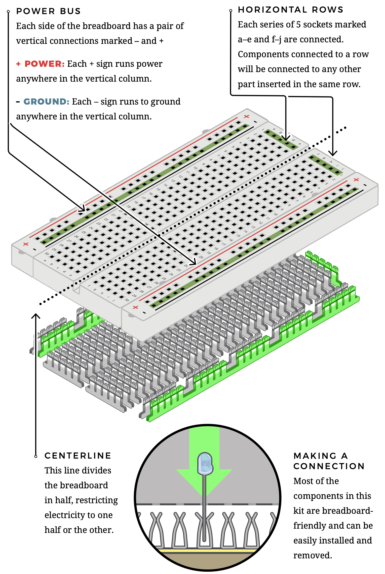
- Power buses: Vertical +/− rails feed power and ground.
- Rows: Groups of 5 holes are connected horizontally.
- Centerline: Splits the board; parts bridge with jumpers or ICs.
- Connections: Parts press into spring contacts—no soldering.
Next Step:
Choose a Coding Platform