
Project Overview
In this circuit, you'll take the night-light concept to the next level by adding an RGB LED, which is three differently colored Light-Emitting Diodes (LEDs) built into one component. RGB stands for Red, Green and Blue, and these three colors can be combined to create any color of the rainbow!
Project 1 - Circuit D

New Components
RGB LED
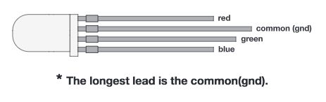
An RGB LED is actually three small LEDs — one red, one green and one blue — inside a normal LED housing. The RGB LED included in this kit has all the internal LEDs share the same ground wire, so there are four legs in total. To turn one color on, ensure ground is connected, then power one of the legs just as you would a regular LED. If you turn on more than one color at a time, you will see the colors start to blend together to form a new color.
New Concepts
Analog Output (Pulse-width Modulation)
You can use the digital pins with the high() and low() commands to turn pins on the RedBoard on (5V) or off (0V), but what if you want to output 2.5V? The RedBoard doesn’t have an Analog Output, but it is really good at switching some digital pins on and off fast enough to simulate an analog output. PWM() can output 2.5 volts by quickly switching a pin on and off so that the pin is only on 50 percent of the time (50% of 5V is 2.5V). By changing the percent of time that a pin is on, from 0 percent (always off) to 100 percent (always on), PWM objects can output any voltage between 0 and 5V. This is what is known as pulse-width modulation (or PWM). By using PWM, you can create many different colors with the RGB LED.
Creating Your own Simple Functions
When programmers want to use a piece of code over and over again, they write a function. The simplest functions are just chunks of code that you give a name to. When you want to run that code, you can “call” the function by typing its name, instead of writing out all of the code. More complicated functions take and return pieces of information from the program (we call these pieces of information parameters). In this circuit, you’ll write functions to turn the RGB LED different colors by just typing that color’s name.
Hookup Guide
WARNING: The RGB LED is polarized. It needs to be inserted in the correct direction
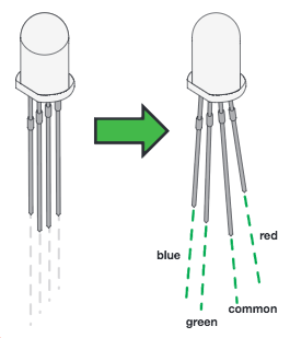
Just like a regular LED, an RGB LED is polarized and only allows electricity to flow in one direction. Pay close attention to the flat edge and to the different length leads. Both are indicators to help orient the LED correctly.
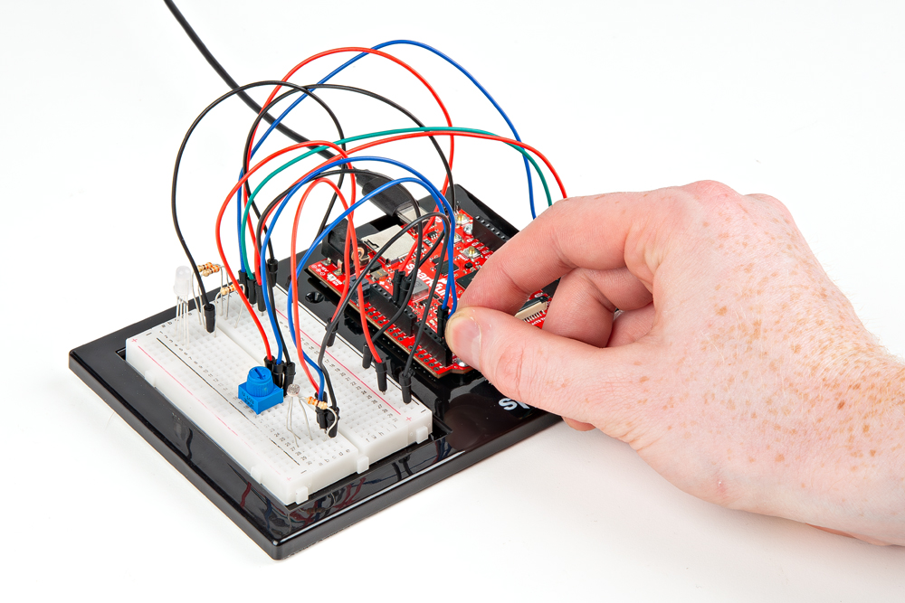
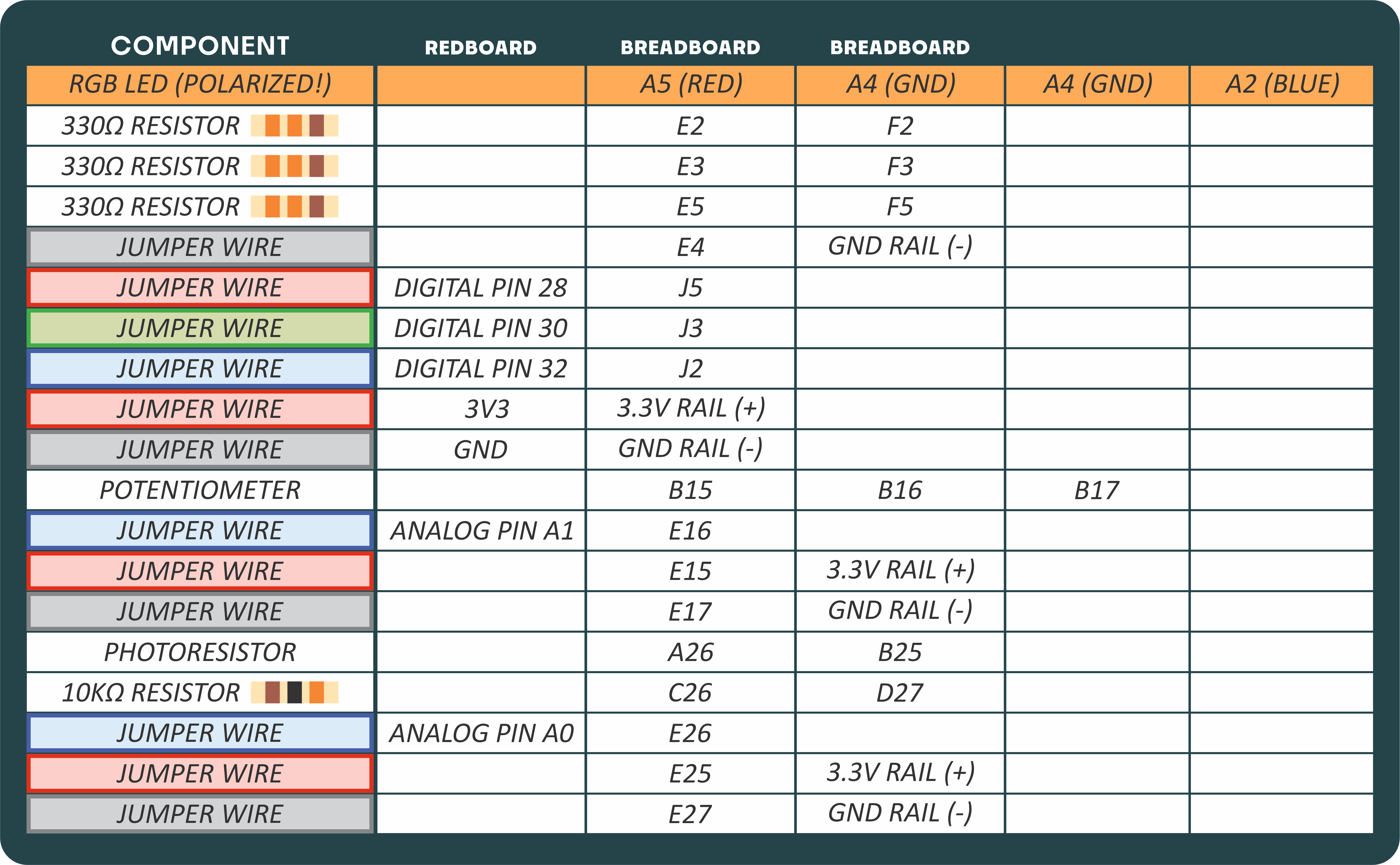
READY TO START HOOKING EVERYTHING UP? Check out the circuit diagram and hookup table below to see how everything is connected.
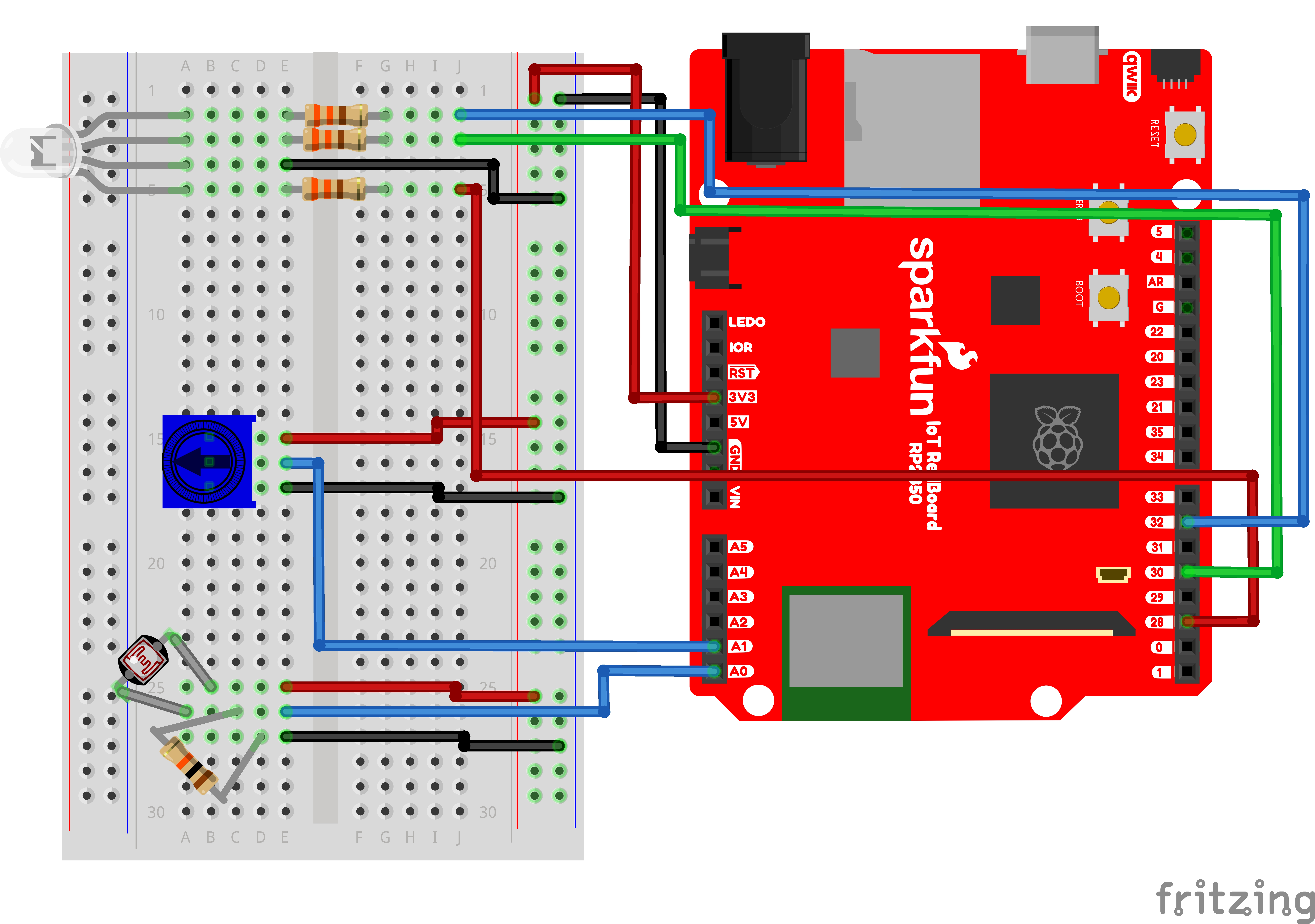
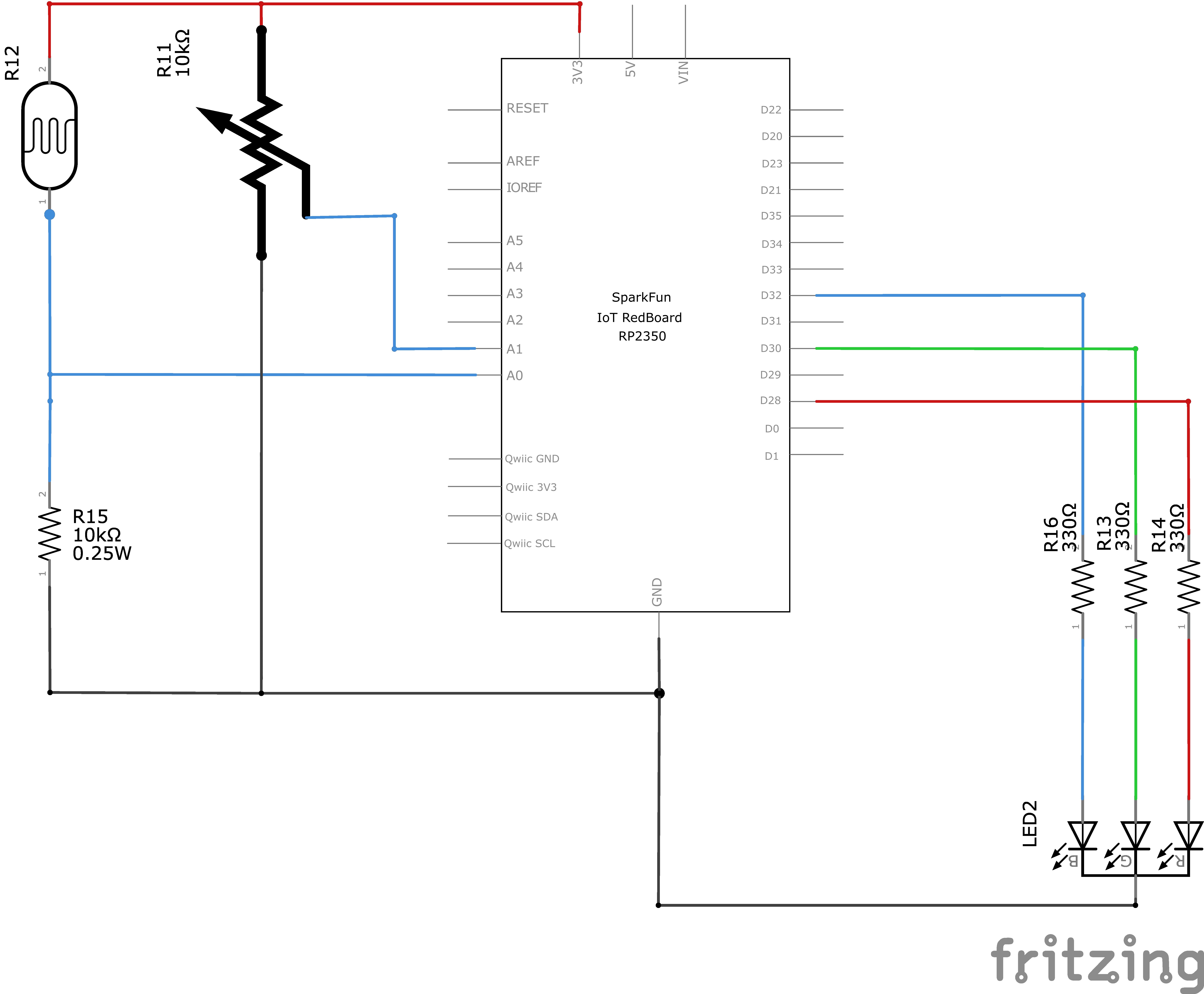
Circuit Diagram
Note for Advanced Users: If you know how to read datasheets and schematics, you can also refer to the schematic below as an alternative.
Hookup Table
Programming the RedBoard
The SparkFun RedBoard IoT is programmed using MicroPython and this project uses MicroPython commands to control the circuit. Before this is possible, a MicroPython tool is needed to communicate with the RedBoard.
Selecting a MicroPython Tool
Our suggested tool is the Thonny IDE. For instructions on how to install and use Thonny, check out our Thonny Guide.
The first step to enter commands on the RedBoard is to select a tool that allows direct interaction with MicroPython.
While a variety of methods exist to communicate with the RedBoard, the following tools are the most popular: Thonny, PyCharm and the command mpremote.
Once you select and install a tool, make sure your RedBoard is connected to your computer, and the micropython tool is connected to the RedBoard. Once connected, you should have access to the MicroPython REPL command line.
Remember that the source files for each SIK circuit are already on your IoT RedBoard RP2350 in the “sik_examples” folder. So if using the suggested Thonny tool, you can select the example for this circuit and run it directly with the green “run current script” button rather than executing lines individually.
Entering MicroPython Commands
Step 1 - Setup
To write to the RGB LED, we need to enable the board pins 32, 30, and 28 that the RGB’s color leads are connected to.
To do this we load the Pin definition for the board
from machine import Pin # Allows us to use Pin to use code to interface with the pins on our boardNext, we load the ADC object to allow us to read our analog pin
from machine import ADCNow we declare our digital pin for the led and our “ADC” to read the analog pin for the photoresistor
led_pin = Pin(34, Pin.OUT) # Create a pin variable for the led pin (pin 34)
photoresistor = ADC(Pin.board.A0) # Create an ADC variable for reading the photoresistor value from analog pin A0
Next, we load the PWM object to allow us to write different colors to our RGB LED by changing the percent of time that a pin is high or low.
from machine import PWM # Allows us to use PWM (pulse-width modulation) to control the brightness of our LEDNow, let’s create our PWM objects that we’ll use later to set colors for the RGB LED.
pwmBlue  = PWM(Pin(32), freq=1000, duty_u16=0) # Create a PWM object on pin 32 with a frequency of 1000Hz and an initial "on time" of 0 (off)
pwmGreen = PWM(Pin(30), freq=1000, duty_u16=0) # Create a PWM object on pin 30 with a frequency of 1000Hz and an initial "on time" of 0 (off)
pwmRed   = PWM(Pin(28), freq=1000, duty_u16=0) # Create a PWM object on pin 28 with a frequency of 1000Hz and an initial "on time" of 0 (off)
Next, lets create our own functions for controlling color. Functions contain several lines of code that we want to reuse often without typing all of them out every time. For example, we would love to set the led to “blue” without having to type three lines of code every time. By putting the lines of code in a function, we just have to type that function’s name to call those three lines of code.
Functions also keep repeated code in the same place. Imagine we wanted to change something about the way our “blue” function behaved. If we had repeated the three lines of code in several places of our program, we would have to fix it for each of those places. But with a function, we would correct it once in our function and leave all the places that function was used untouched.
# Let's create functions for various colors that we can call later

# Since our PWM "on time" or duty cycle is 16 bits, it is a value between 0 and 65535.
# It's useful to store a variable for maximum brightness so we can use percentages of it easily.
kMaximumBrightness = 65535  # Maximum brightness value for PWM

# These are "functions" that we can "call" to set the color of the LED.
# Notice the "def" keyword, which is used to define a function in Python.
# Now, we can call these later by just typing their names like `red()`, `green()`, etc.
# And all the code inside the function will run.

def red():
    # The "duty_u16" method sets the duty cycle or "on time" for the PWM pin.
    pwmRed.duty_u16(kMaximumBrightness)  # Set the red LED to full brightness
    pwmGreen.duty_u16(0)    # Turn off the green LED
    pwmBlue.duty_u16(0)     # Turn off the blue LED

def orange():
    pwmRed.duty_u16(kMaximumBrightness)  # Set the red LED to full brightness
    pwmGreen.duty_u16(int(kMaximumBrightness * 0.25))  # Set the green LED to quarter brightness (by multiplying by 0.5)
    pwmBlue.duty_u16(0)     # Turn off the blue LED

def yellow():
    pwmRed.duty_u16(kMaximumBrightness)  # Set the red LED to full brightness
    pwmGreen.duty_u16(kMaximumBrightness)  # Set the green LED to full brightness
    pwmBlue.duty_u16(0)     # Turn off the blue LED

def green():
    pwmRed.duty_u16(0)      # Turn off the red LED
    pwmGreen.duty_u16(kMaximumBrightness)  # Set the green LED to full brightness
    pwmBlue.duty_u16(0)     # Turn off the blue LED

def cyan():
    pwmRed.duty_u16(0)      # Turn off the red LED
    pwmGreen.duty_u16(kMaximumBrightness)  # Set the green LED to full brightness
    pwmBlue.duty_u16(kMaximumBrightness)  # Set the blue LED to full brightness

def blue():
    pwmRed.duty_u16(0)      # Turn off the red LED
    pwmGreen.duty_u16(0)    # Turn off the green LED
    pwmBlue.duty_u16(kMaximumBrightness)  # Set the blue LED to full brightness

def magenta():
    pwmRed.duty_u16(kMaximumBrightness)  # Set the red LED to full brightness
    pwmGreen.duty_u16(0)    # Turn off the green LED
    pwmBlue.duty_u16(kMaximumBrightness)  # Set the blue LED to full brightness

def turnOff():
    pwmRed.duty_u16(0)      # Turn off the red LED
    pwmGreen.duty_u16(0)    # Turn off the green LED
    pwmBlue.duty_u16(0)     # Turn off the blue LED
Now lets try turning our LED Red, by calling our first function!
# Call our "red" function from above and all of the line of code inside it will run, which will turn the LED to red
red()

# Try messing with the other functions by calling them instead of `red()`.
# For example, you can try `green()`, `blue()`, `yellow()`, etc.
Awesome, now that you’ve mastered using functions and PWM to change the color of your RGB LED, you’ve learned the last of the lessons for project 1! It’s time to put everything you’ve learned together by running the following program. It uses our pins and functions above and adds back in some content from our previous project 1 circuits.
import time # Import the time module to use sleep for delays

# Remember, we've already defined our RGB pins and functions above.
# Make sure you have run the cells above this one first!!!
photoresistor = ADC(Pin.board.A0) # Create an ADC variable for reading the photoresistor value from analog pin A0
potentiometer = ADC(Pin.board.A1) # Create an ADC variable for reading the potentiometer value from analog pin A1

# We'll set our photo-resistor threshold to a quarter of the maximum value of the ADC reading (65535)
threshold = 65535 / 4
potentiometerMax = 65535  # Maximum value for the potentiometer reading

# Infinite loop to continously read the photoresistor and potentiometer values
while True:
    photoValue = photoresistor.read_u16()  # Read the photoresistor value (0 to 65535)
    potPosition = potentiometer.read_u16()  # Read the potentiometer value (0 to 65535)
    # Print the values to the console
    print(f"Photoresistor Value: {photoValue: 5}, Potentiometer Value: {potPosition : 5}", end='\r') # Print our readings (don't mind the fanciness of this line it just makes the print format nicely)

    # Check if the photoresistor value is below the threshold
    if photoValue < threshold:
        # If the photoresistor value is below the threshold, set the LED color based on the potentiometer position
        # Let's split the range 0 - 65535 into 7 equal(ish) parts for different colors
        if potPosition > 0 and potPosition < 9362:
            red()
        if potPosition >= 9362 and potPosition < 18725:
            orange()
        if potPosition >= 18725 and potPosition < 28087:
            yellow()
        if potPosition >= 28087 and potPosition < 37450:
            green()
        if potPosition >= 37450 and potPosition < 46812:
            cyan()
        if potPosition >= 46812 and potPosition < 56175:
            blue()
        if potPosition >= 56175 and potPosition <= 65535:
            magenta()

    else: # Note that this "else" aligns with the photovalue < Threshold condition above.
        turnOff()  # Turn off the LED if the photoresistor value is above the threshold

    time.sleep(0.250)  # Sleep for 0.25 seconds to avoid flooding the console with prints
What You Should See
This program puts together the photoresistor, potentiometer, and RGB led to create a customizable night light. When the light of your room is below the threshold, the RGB will turn on. The color of the RGB can then be set with the potentiometer
Coding Challenges
| Challenge | Description |
|---|---|
| Add more colors | You can create many more colors with the RGB LED. Use the duty_u16() function to blend different values of red, green and blue together to make even more colors. You can divide the potentiometer value up more and make more nested if statements so that you can have more colors as you twist the knob. |
| Multi color blink | Try using delays and multiple color functions to have your RGB LED change between multiple colors. |
| Change the threshold | Try setting your threshold variable by reading the value of a potentiometer with read_u16(). By turning the potentiometer, you can then change the threshold level and adjust your night-light for different rooms. |
| Fading the LED | Try using a loop with the duty_u16() to get your LED to pulse gently or smoothly transition between colors. |
Troubleshooting
| Problem | Solution |
|---|---|
| The LED never turns on or off | Ensure you are connected to the correct serial port and have run the correct code example (or properly copied and pasted all code blocks from this guide in-order) |
You’ve Completed Circuit 1D!
You’ve Also Completed all of Project 1!
Continue to project 2 to learn about sound!