
Project Overview
In this circuit, you will learn how to wire a servo and control it with code. Servo motors can be told to move to a specific position and stay there. Low-cost servo motors were originally used to steer remote-controlled airplanes and cars, but they have become popular for any project where precise movement is needed.
Project 3 - Circuit A

New Components
Servo Motors
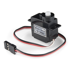
Regular DC motors have two wires. When you hook the wires up to power, the motor spins around and around. Servo motors, on the other hand, have three wires: one for power, one for ground and one for signal. When you send the right signal through the signal wire, the servo will move to a specific angle and stay there. Common servos rotate over a range of 0° to 180°. The signal that is sent is a PWM signal, the same used to control the RGB LED in Project 1.
New Concepts
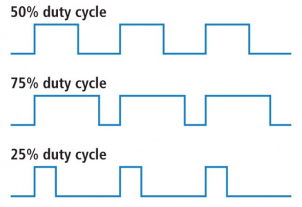
Duty Cycle
The Pulse Width Modulation (PWM) hardware available on a microcontroller is a great way to generate servo control signals. When talking about how long a PWM signal is on, this is referred to as duty cycle. Duty cycle is measured in percentage. The percentage of duty cycle specifically describes the percentage of time a digital signal is on over an interval or period of time. The variation in the duty cycle tells the servo which position to go to in its rotation.
MicroPython Modules/Libraries
Writing code that sends precise PWM signals to the servo would be time consuming and would require a lot more knowledge about the servo. Luckily, MicroPython has hundreds of built-in and user-submitted containers of code that are called modules or libraries. Lets use the following user-submitted servo library.
To use a MicroPython module, all you have to do is “import” it (or copy its code directly). To use the Servo Library/Class from the sik_utilities module that’s already loaded on your kit, you would add the following line to the top of your code:
from sik_utilities import Servo # Import the servo class from the sik_utilities moduleObjects and Methods
To use the servo library, you will have to start by creating a Servo object, like this:
myServo = Servo(pin_id=28)Objects look a lot like variables, but they can do much more. Objects can store values, and they can have their own functions, which are called methods.
The most used method that a servo object has is .write().
The write method takes one parameter, a number from 0 to 180, and moves the servo arm to the specified position (in this case, degree 90).
Why would we want to go to the trouble of making an object and a method instead of just sending a servo control signal directly over a pin? First, the servo object does the work of translating our desired position into a signal that the servo can read. Second, using objects makes it easy for us to add and control more than one servo.
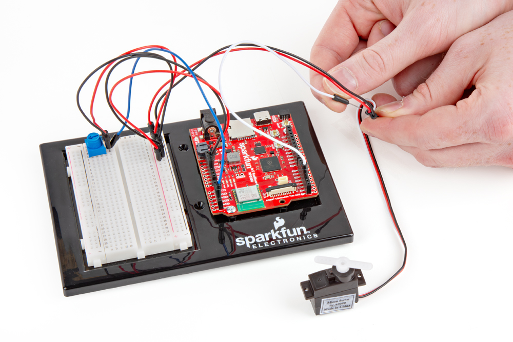
Hookup Guide
Servo motor connectors are polarized, but there is no place to attach them directly. Instead, connect three jumper wires to the female 3-pin header on the servo. This will make it so you can connect the servo to the breadboard.
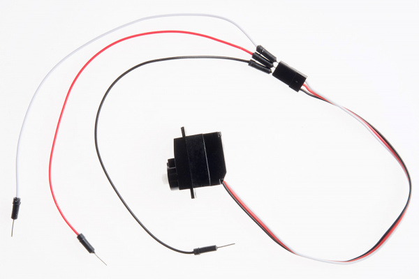
The servo wires are color coded to make hookup simple. The pin-out is as follows
| Pin | Description |
|---|---|
| White | Signal - PWM In |
| Red | Power (5V) |
| Black | Ground (GND) |
Included with your servo motor you will find a variety of motor mounts that connect to the shaft of your servo. You may choose to attach any mount you wish for this circuit. It will serve as a visual aid, making it easier to see the servo spin. The mounts will also come in handy at the end of this project.
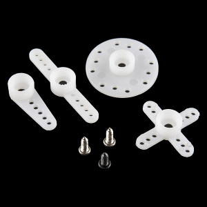
The various motor mounts included with your servo motor
Affix the Servo (Optional)
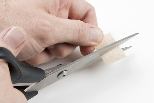
Included in your SIK is a strip of Dual Lock™. Cut a piece off the strip that is about ⅝ inch or 1.6cm. Then cut that strip in half to get two pieces that are roughly ⅝ inch x 1/2 inch or 1.6cm x 1.3cm.
Peel off the adheseive backing, and stick one half on the bottom of the servo motor.
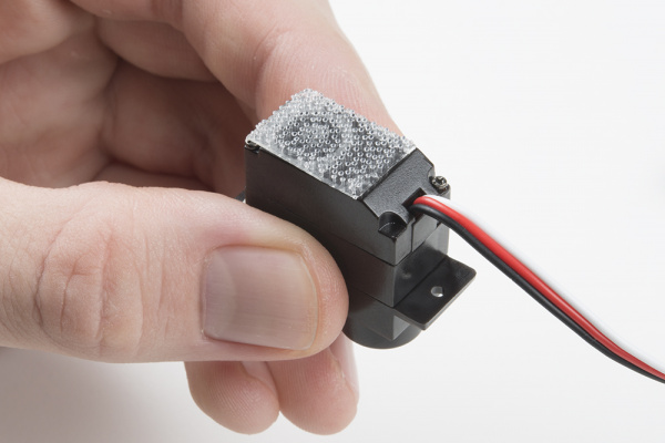
Stick the other half anywhere on the breadboard baseplate you want. Firmly press the bottom of the servo to the baseplate to temporarily adhere the two pieces of Dual Lock together. This will help stabilize the servo motor as it moves about.
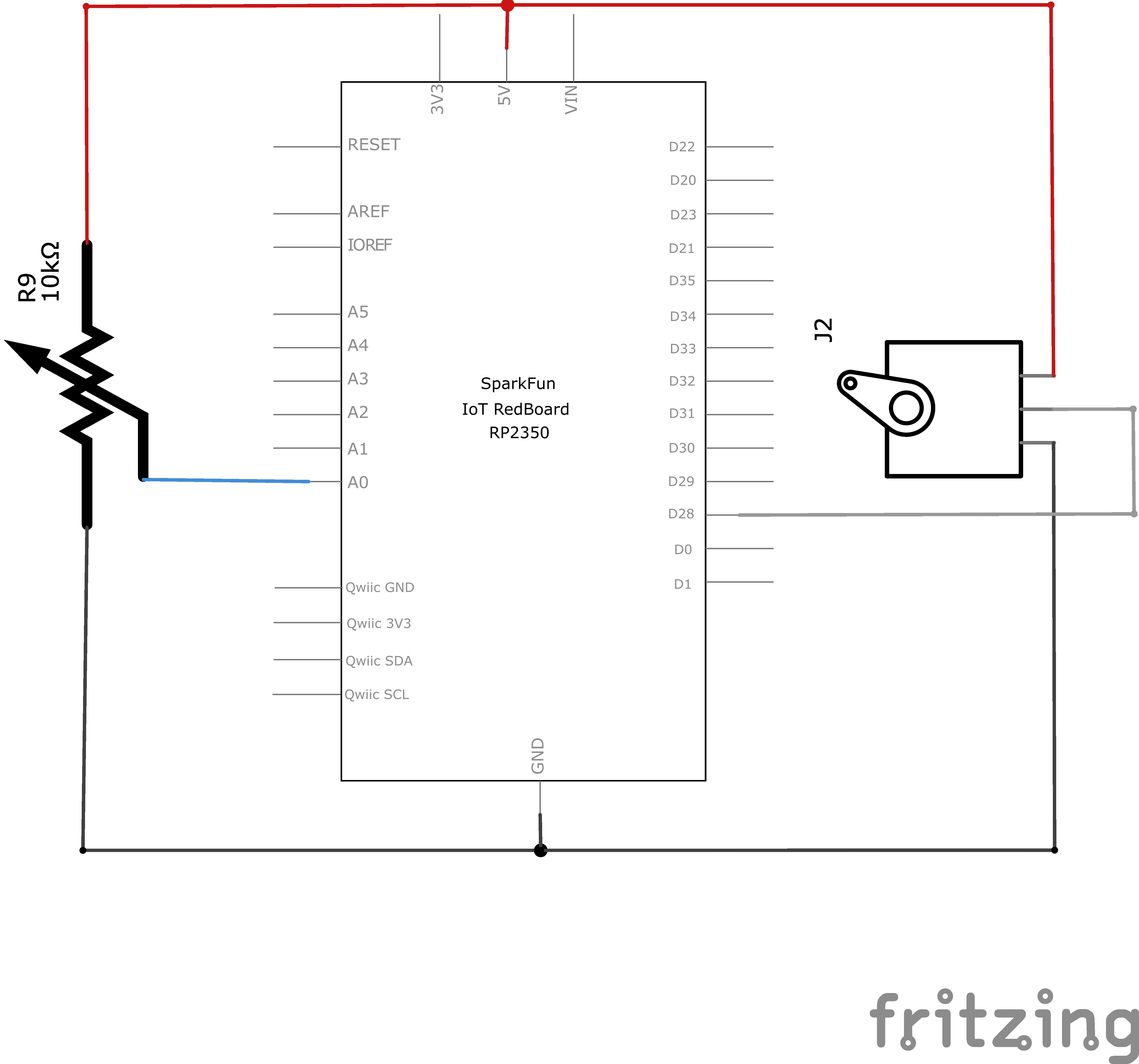
READY TO START HOOKING EVERYTHING UP? Check out the circuit diagram and hookup table below to see how everything is connected.
Circuit Diagram
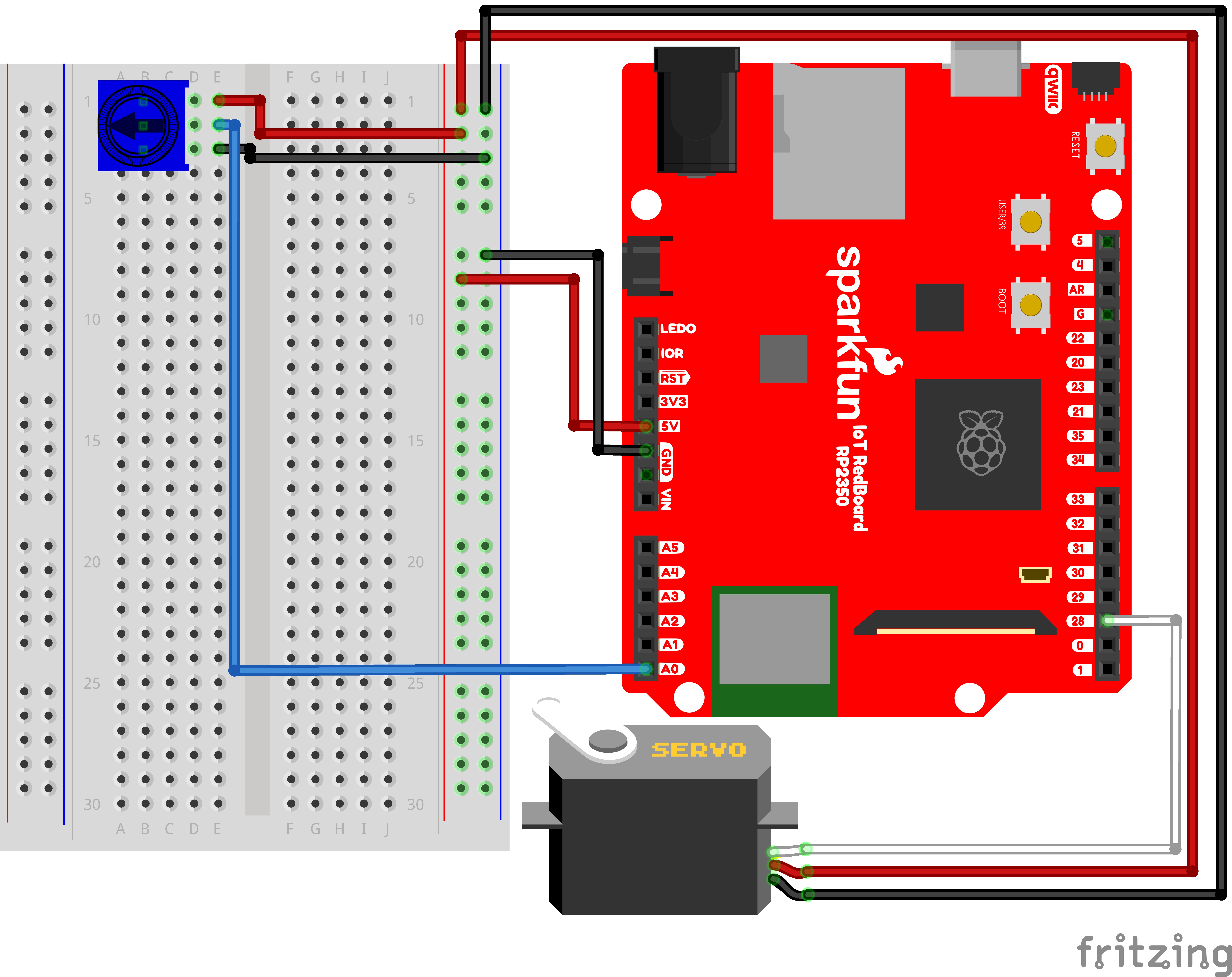
Note for Advanced Users: If you know how to read datasheets and schematics, you can also refer to the schematic below as an alternative.
Hookup Table
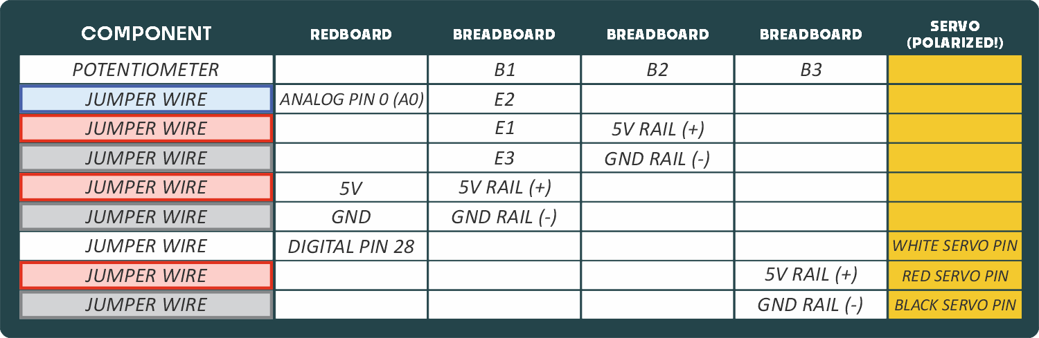
NOTE: Carefully ensure the yellow Polarized connections are made properly or it could damage your servo.
Programming the RedBoard
The SparkFun RedBoard IoT is programmed using MicroPython and this project uses MicroPython commands to control the circuit. Before this is possible, a MicroPython tool is needed to communicate with the RedBoard.
Selecting a MicroPython Tool
Our suggested tool is the Thonny IDE. For instructions on how to install and use Thonny, check out our Thonny Guide.
The first step to enter commands on the RedBoard is to select a tool that allows direct interaction with MicroPython.
While a variety of methods exist to communicate with the RedBoard, the following tools are the most popular: Thonny, PyCharm and the command mpremote.
Once you select and install a tool, make sure your RedBoard is connected to your computer, and the micropython tool is connected to the RedBoard. Once connected, you should have access to the MicroPython REPL command line.
Remember that the source files for each SIK circuit are already on your IoT RedBoard RP2350 in the “sik_examples” folder. So if using the suggested Thonny tool, you can select the example for this circuit and run it directly with the green “run current script” button rather than executing lines individually.
Entering MicroPython Commands
Step 1 - Setup
Let’s use the servo module we discussed earlier (remember to run previous cells before running those below).
Lets start by importing any of the libaries we plan on using and creating a Servo object.
from machine import Pin # Allows us to use "Pin" to use code to interface with the pins on our board
from machine import ADC # Allows us to use "ADC" (analog-to-digital conversion) to read from our analog pin
from sik_utilities import Servo  # Allows us to use "Servo" to control a servo motor

potentiometer = ADC(Pin.board.A0) # Create an ADC variable for reading the potentiometer value from analog pin A0

# Create a Servo object on pin 28 (this is the pin we will use to control the servo motor)
myServo = Servo(pin_id=28)
Step 2 - Writing to the Servo
Now let’s create a loop where we read the potentiometer value and move the servo based on the potentiometer position.
# Infinite loop to read the potentiometer value and control the servo motor
while True:
    pot_value = potentiometer.read_u16()  # Read the potentiometer value (0-65535)
    angle = (pot_value / 65535) * 180  # Convert the value to an angle (0-180 degrees)

    myServo.write(angle)  # Write the angle to the servo motor
What You Should See
Turning the potentiometer will cause the servo to turn.
Coding Challenges
| Challenge | Description |
|---|---|
| Reverse the direction | Try making the servo move in the opposite direction to the potentiometer. |
| Change the range | Try altering the angle equation such that moving the potentiometer a lot only moves the servo a little. |
| Swap in a different sensor | Try swapping a light sensor in for the potentiometer. You have just made a dial that reads how much light is present! |
Troubleshooting
| Problem | Solution |
|---|---|
| The servo doesn’t move | Check the wiring on your servo. Make sure that the red wire on the servo cord is connected to 5V, the black wire is connected to GND and the white signal wire is connected to the correct pin. |
| The servo is twitching | Although these servos are supposed to move from 0 to 180 degrees, sometimes sending them to the extremes of their range causes them to twitch (the servo is trying to move farther than it can). Make sure that you aren’t telling the servo to move outside of the 20-160 degree range. |
You’ve Completed Circuit 3A!
Continue to circuit 3B to learn about distance sensors.