
Project Overview
Distance sensors are amazing tools with all kinds of uses. They can sense the presence of an object, they can be used in experiments to calculate speed and acceleration, and they can be used in robotics to avoid obstacles. This circuit will walk you through the basics of using an ultrasonic distance sensor, which measures distance using sound waves!
Project 3 - Circuit B

New Components
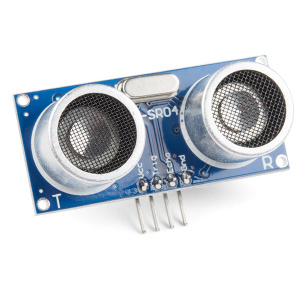
Ultrasonic Distance Sensor
Distance sensors work by sending pulses of light or sound out from a transmitter, then timing how long it takes for the signals to bounce off an object and return to a receiver (just like sonar). Some sensors use infrared light, some use lasers, and some, like the HC-SR04 included in your kit, use ultrasonic sound (sound so high-pitched that you can’t hear it).
New Concepts
Datasheets
When working with electronics, datasheets are your best friend. Datasheets contain all the relevant information needed to get you up and running with a part. In this circuit, we are calculating distance based on the time it takes sound waves to be transmitted, bounce off an object and then be received. But, how can we tell distance from that information? The answer lies in the datasheet for the distance sensor. In it, you can find the equation the program needs to interpret distance from the time it takes the sound wave to travel.
Elif Statements
In the night-light circuit, you used an if/else statement to run one set of code when a logic statement was true, and a different set of code when it was false. What if you wanted to have more than two options? Elif statements (short for “else if”) let you run as many logical tests as you want in one if statement. For example, in the code for this circuit, there is an if statement that flows like this:
- If the distance is less than 10, make the RGB LED red.
- Elif the distance is more than 10 but less than 20, make the RGB LED yellow.
- Else make the RGB LED green.
If you wanted to have four or five colors for different distances, you could add more elif statements.
Elif statements are different from nested if statements in that only one of the statements above can be true, whereas you could have multiple nested if statements that could be true.
Hookup Guide
⚠️ Warning For Polarized Components: Pay special attention to the component’s markings indicating how to place it on the breadboard. Polarized components can only be connected to a circuit in one direction.
The distance sensor is polarized. Take note of the pin labels when connecting your circuit.
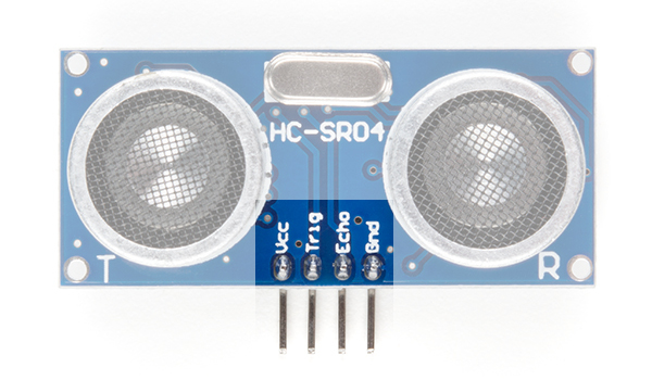
The following table describes the function of each pin on the distance sensor:
| Pin | Description |
|---|---|
| VCC | Power (5V) |
| Trig | Trigger Pulse Input: Sends bursts of ultrasound at 40kHz. |
| Echo | Echo Pulse Output: Receives echo signal. Range is calculated by the proportion of trigger signal sent and echo signal received. |
| GND | Ground (0V) |
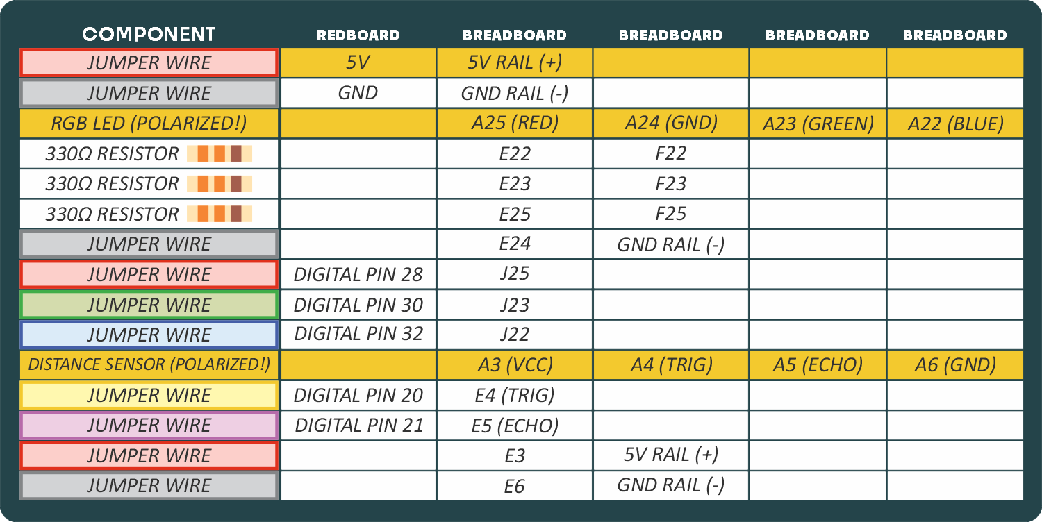
READY TO START HOOKING EVERYTHING UP? Check out the circuit diagram and hookup table below to see how everything is connected.
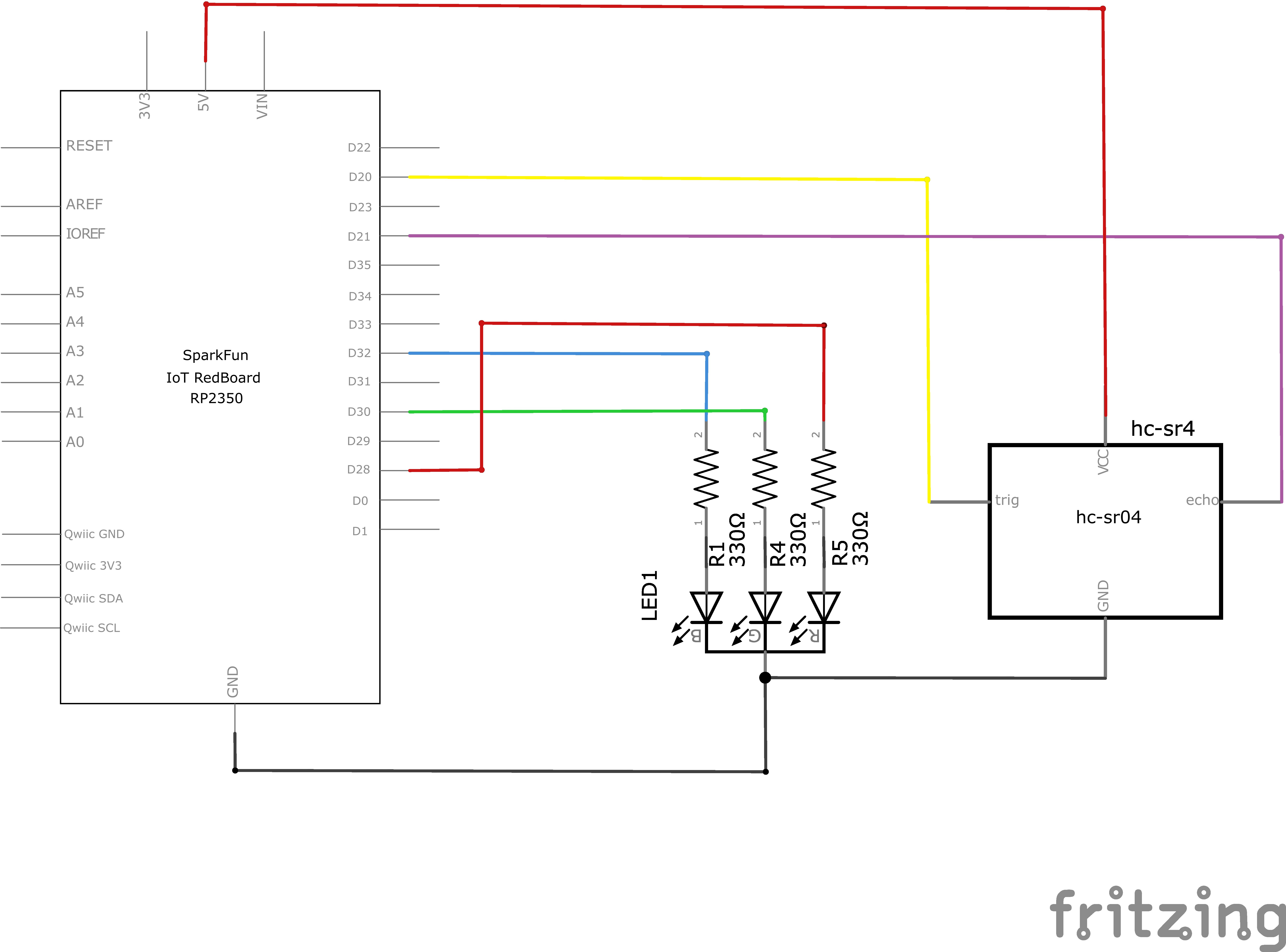
Circuit Diagram
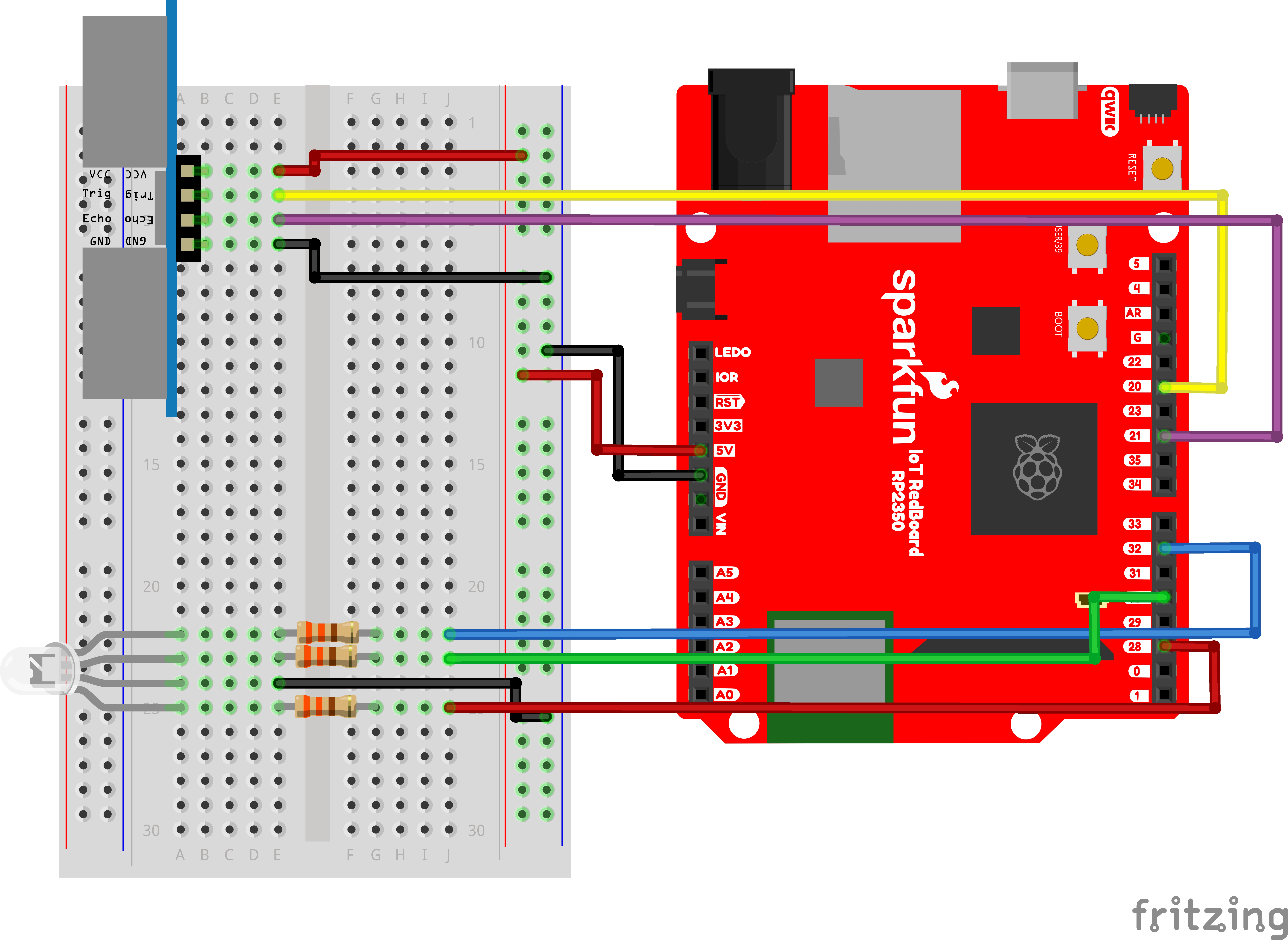
Note for Advanced Users: If you know how to read datasheets and schematics, you can also refer to the schematic below as an alternative.
Hookup Table
Programming the RedBoard
The SparkFun RedBoard IoT is programmed using MicroPython and this project uses MicroPython commands to control the circuit. Before this is possible, a MicroPython tool is needed to communicate with the RedBoard.
Selecting a MicroPython Tool
Our suggested tool is the Thonny IDE. For instructions on how to install and use Thonny, check out our Thonny Guide.
The first step to enter commands on the RedBoard is to select a tool that allows direct interaction with MicroPython.
While a variety of methods exist to communicate with the RedBoard, the following tools are the most popular: Thonny, PyCharm and the command mpremote.
Once you select and install a tool, make sure your RedBoard is connected to your computer, and the micropython tool is connected to the RedBoard. Once connected, you should have access to the MicroPython REPL command line.
Remember that the source files for each SIK circuit are already on your IoT RedBoard RP2350 in the “sik_examples” folder. So if using the suggested Thonny tool, you can select the example for this circuit and run it directly with the green “run current script” button rather than executing lines individually.
Entering MicroPython Commands
Step 1 - Setup
Lets start by importing any of the libaries we plan on using and setting up our pins.
from machine import Pin # Allows us to use "Pin" to use code to interface with the pins on our board
from machine import PWM # Allows us to use "PWM" (pulse-width modulation) to control the brightness of our LED

pwmBlue  = PWM(Pin(32), freq=1000, duty_u16=0) # Create a PWM object on pin 28 with a frequency of 1000Hz and an initial "on time" of 0 (off)
pwmGreen = PWM(Pin(30), freq=1000, duty_u16=0) # Create a PWM object on pin 27 with a frequency of 1000Hz and an initial "on time" of 0 (off)
pwmRed   = PWM(Pin(28), freq=1000, duty_u16=0) # Create a PWM object on pin 26 with a frequency of 1000Hz and an initial "on time" of 0 (off)

trigPin = Pin(20, Pin.OUT) # Create a pin object for the trigger pin (pin 20) and set it as an output
echoPin = Pin(21, Pin.IN) # Create a pin object for the echo pin (pin 21) and set it as an input
Step 2 - Measuring Distance
Next, let’s create a function to calculate distance. We’ll send out an ultrasonic pulse on the trigPin and then measure how long it takes for the pulse to bounce back to the sensor by using the built-in “time_pulse_us” function on the echo pin.
from time import sleep_us
from machine import time_pulse_us

def get_distance():
    trigPin.high()
    sleep_us(10) # Send at least a 10 microsecond pulse to the trigger pin to start the measurement
    trigPin.low() # Set the trigger pin low to stop the measurement

    echoTime = time_pulse_us(echoPin, 1)

    calculatedDistance = echoTime / 148.0 #calculate the distance of the object that reflected the pulse (half the bounce time multiplied by the speed of sound)

    return calculatedDistance # Return the calculated distance
Step 3 - Putting it all together
Now let’s put the functions we created together along with some LED control. Let’s create a loop where we read the distance from the ultrasonic sensor and update the LED color depending on how far objects are from the sensor.
from time import sleep

# Infinite loop to read the distance sensor and update the RGB LED colors based on the distance
while True:
    distance = get_distance() # Get the distance from the sensor
    print(f"Distance (in): {distance: 5}", end='\r') # Print our readings (don't mind the fanciness of this line it just makes the print format nicely)

    if distance <= 10:
        # Make the RGB LED red
        pwmRed.duty_u16(65535)
        pwmGreen.duty_u16(0)
        pwmBlue.duty_u16(0)

    elif distance < 20:
        # Make the RGB LED yellow
        pwmRed.duty_u16(65535)
        pwmGreen.duty_u16(32768)
        pwmBlue.duty_u16(0)

    else:
        # Make the RGB LED green
        pwmRed.duty_u16(0)
        pwmGreen.duty_u16(65535)
        pwmBlue.duty_u16(0)

    sleep(0.050) # Sleep for 50 ms between each reading
What You Should See
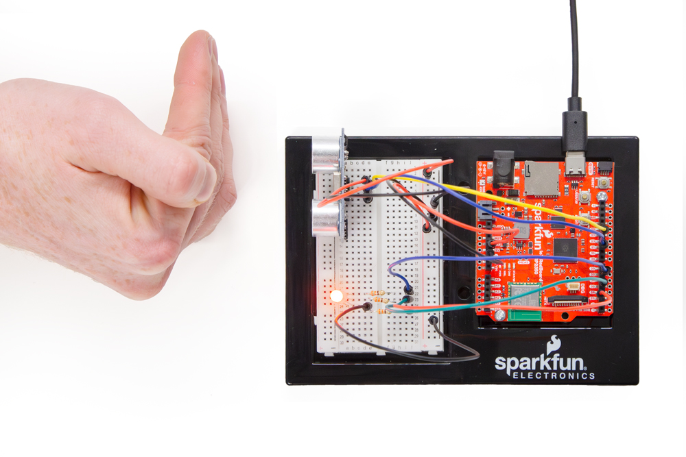
Move your hand or a large, flat object closer and farther away from the distance sensor. As the object approaches, the light will change from green to yellow to red.
Coding Challenges
| Challenge | Description |
|---|---|
| Change the limits of the distance sensor | Try editing the values in the logic statements so that the RGB LED changes color at different distances. |
| Change the units of the distance sensor | Try editing the code so that the distance sensor outputs a different unit of length, such as centimeters or feet. |
| Add a fourth color | Try adding another elif statement so that there are four different colors instead of three. |
Troubleshooting
| Problem | Solution |
|---|---|
| The RGB LED colors aren't working or a color is missing | Check the connection for the wire and resistor connected to each leg of the LED. Ensure the RGB LED is inserted in the correct orientation. |
| The distance sensor doesn’t seem to work | You should see a stream of distances being printed in the monitor. If they are all reading 0 or jump around, then check the wiring on your sensor. |
| The distance sensor still doesn’t work | Ultrasonic noise pollution will interfere with your distance sensor readings. If you aim two distance sensors at each other, they will confuse each other. Some air-conditioning systems may also emit noises in the ultrasonic range. Try pointing your sensor away from the other distance sensors or changing to a different location. |
You’ve Completed Circuit 3B!
Continue to circuit 3C to create a fun motion alarm!