
Project Overview
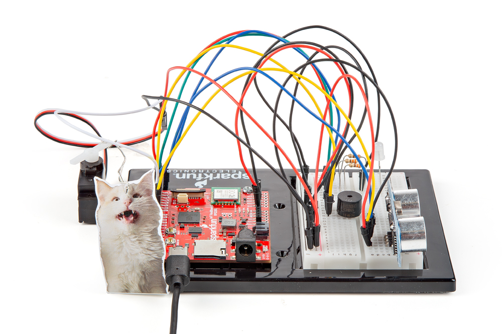
Time to take your distance sensor project to the next level. Let’s imagine that you want to stop your cat from prowling around your countertop. This circuit will use light, sound and motion to scare away your cat when it is detected by the distance sensor. Using a servo motor, you can add a moving pop-up to animate your alarm. Don’t have a cat? No problem! This circuit can be adapted for a variety of projects such as a room alarm, an automated pop-up story, an automatic treat dispenser and so much more. Let your imagination run wild with this project.
Project 3 - Circuit C

Additional Materials (Not Included)
The following materials are optional. The circuit can be completed without these items.
- Paper
- Scissors
- Scotch™ Tape
- Markers/Pen
- Paper Clip
- Needle-Nose Pliers
New Concepts
Getting Creative With Mechanisms
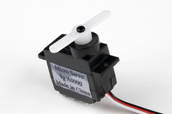
This circuit gets really fun when you start to use your servo to animate the world around you. To do this, you’ll need to connect your servo to some physical mechanisms. Tape and hot glue are easy ways to connect things to your servo. You can also loop a paper clip through the small holes in the servo arm to serve as a linkage. See the Hardware Hookup section below for more information.
Linkage rods are found on many RC airplanes which use servo motors to control the ailerons, elevators and rudder.
Hookup Guide
If you have opted for the extra materials, use the following instructions to create the moving pop-up for your cat alarm.
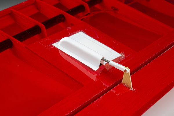
To begin, attach your servo to the baseplate using Dual Lock, as described in Circuit 3A.
Attach the servo mount of your choice. It is recommended you wait until after you have uploaded your code to ensure the mount is in the best position before screwing on the mount. The screw is optional, but it will make for a more robust mechanism.
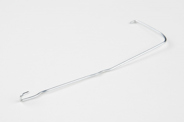
Next, use needle-nose pliers to bend the paper clip straight. Imagine a 3D space. The straight clip is the X-axis. Bend one end of the paper clip 90 degrees along the Y-axis. The bent segment should be about 1 inch or 2.5cm long. Then bend the other end along the Z-axis. This bend should be about 1/8 inch or 3mm long. Repeat this bend once more back toward the X-axis, making a hook shape. You should now have a linkage rod that looks something like this:
Attach the hook end of the linkage rod to the end hole on your servo mount.
Cut out the pop-up image of your choice. We chose this public domain menacing cat image (http://bit.ly/2vinyE1). The image you choose should be about 2.5 inches x 2.5 inches and can be drawn or printed. Leave a rectangular strip of paper under the image that is about 2 inches long. Fold along the bottom of the image. Tape the pop-up to the underside of the breadboard baseplate on the same side to which the servo is connected.
Last, tape the free end of the rod to the back of your pop-up image.
Once you have the rest of the circuit built and the code uploaded, you can fine-tune your moving pop-up and make any necessary adjustments. Remember to wait until these adjustments have been made before you screw the servo mount onto the motor.
READY TO START HOOKING EVERYTHING UP? Check out the circuit diagram and hookup table below to see how everything is connected.
Circuit Diagram
Note for Advanced Users: If you know how to read datasheets and schematics, you can also refer to the schematic below as an alternative.
Hookup Table
Programming the RedBoard
The SparkFun RedBoard IoT is programmed using MicroPython and this project uses MicroPython commands to control the circuit. Before this is possible, a MicroPython tool is needed to communicate with the RedBoard.
Selecting a MicroPython Tool
Our suggested tool is the Thonny IDE. For instructions on how to install and use Thonny, check out our Thonny Guide.
The first step to enter commands on the RedBoard is to select a tool that allows direct interaction with MicroPython.
While a variety of methods exist to communicate with the RedBoard, the following tools are the most popular: Thonny, PyCharm and the command mpremote.
Once you select and install a tool, make sure your RedBoard is connected to your computer, and the micropython tool is connected to the RedBoard. Once connected, you should have access to the MicroPython REPL command line.
Remember that the source files for each SIK circuit are already on your IoT RedBoard RP2350 in the “sik_examples” folder. So if using the suggested Thonny tool, you can select the example for this circuit and run it directly with the green “run current script” button rather than executing lines individually.
Entering MicroPython Commands
Step 1 - Setup
Remember the servo module used in circuit 3A? Let’s use it again! Lets also import any of the other libaries we plan on using and setting up our pins.
from machine import Pin # Allows us to use "Pin" to use code to interface with the pins on our board
from machine import PWM # Allows us to use "PWM" (pulse-width modulation) to control the brightness of our LED
from sik_utilities import Servo  # Allows us to use "Servo" to control a servo motor

# LEDs
pwmRed   = PWM(Pin(28), freq=1000, duty_u16=0) # Create a PWM object on pin 28 with a frequency of 1000Hz and an initial "on time" of 0 (off)
pwmBlue  = PWM(Pin(32), freq=1000, duty_u16=0) # Create a PWM object on pin 32 with a frequency of 1000Hz and an initial "on time" of 0 (off)
pwmGreen = PWM(Pin(30), freq=1000, duty_u16=0) # Create a PWM object on pin 30 with a frequency of 1000Hz and an initial "on time" of 0 (off)

# Distance Sensor
trigPin = Pin(20, Pin.OUT) # Create a pin object for the trigger pin (pin 20) and set it as an output
echoPin = Pin(21, Pin.IN) # Create a pin object for the echo pin (pin 21) and set it as an input

# Buzzer
pwmSpeaker  = PWM(Pin(34), freq=0, duty_u16=0) # Create a PWM object on pin 34 with a frequency of 0Hz and an initial "on time" of 0 (off)

# Servo
myServo = Servo(pin_id=35)
Step 2 - Measuring Distance
Next, let’s create a function to calculate distance. We’ll send out an ultrasonic pulse on the trigPin and then measure how long it takes for the pulse to bounce back to the sensor by using the built-in “time_pulse_us” function on the echo pin.
from time import sleep_us
from machine import time_pulse_us

def get_distance():
    trigPin.high()
    sleep_us(10) # Send at least a 10 microsecond pulse to the trigger pin to start the measurement
    trigPin.low() # Set the trigger pin low to stop the measurement

    echoTime = time_pulse_us(echoPin, 1)

    calculatedDistance = echoTime / 148.0 #calculate the distance of the object that reflected the pulse (half the bounce time multiplied by the speed of sound)

    return calculatedDistance # Return the calculated distance
Step 3 - Putting it all together
Now let’s put the functions we created together along with some LED control. Let’s create a loop where we read the distance from the ultrasonic sensor and update the LED color, servo, and buzzer depending on how far objects are from the sensor.
from time import sleep

# Infinite loop to read the distance sensor and update the RGB LED colors based on the distance
while True:
    distance = get_distance() # Get the distance from the sensor
    print(f"Distance (in): {distance: 5}", end='\r') # Print our readings (don't mind the fanciness of this line it just makes the print format nicely)

    if distance <= 10:
        # Make the RGB LED red
        pwmRed.duty_u16(65535)
        pwmGreen.duty_u16(0)
        pwmBlue.duty_u16(0)

        # This code wiggles the servo and beeps the buzzer
        pwmSpeaker.freq(272)            # Buzz the buzzer at 272 Hz
        pwmSpeaker.duty_u16(32768)      # Enable the buzzer at 50% duty cycle
        myServo.write(10)               # Move the servo to 10 degrees
        sleep(0.100)                    # Wait 100 milliseconds

        pwmSpeaker.duty_u16(0)          # Turn off the buzzer
        myServo.write(150)              # Move the servo to 150 degrees
        sleep(0.100)                    # Wait 100 milliseconds

    elif distance < 20:
        # Make the RGB LED yellow
        pwmRed.duty_u16(65535)
        pwmGreen.duty_u16(32768)
        pwmBlue.duty_u16(0)

    else:
        # Make the RGB LED green
        pwmRed.duty_u16(0)
        pwmGreen.duty_u16(65535)
        pwmBlue.duty_u16(0)

    sleep(0.050) # Sleep for 50 ms between each reading
What You Should See
The RGB LED will behave as in your last circuit. It will be green when objects are far, yellow when they are midrange and red when they are close. When an object is close the buzzer will also beep, and the servo will rotate back and forth.
Coding Challenges
| Challenge | Description |
|---|---|
| Change the servo behavior | Try changing the way that your servo behaves when the distance sensor is triggered. |
| Change the alarm settings | Try altering the code so the alarm goes off from much farther or closer distances. |
| Create a different mechanism | Try your hand at making different objects move with your servo motor. Make an interactive pop-up story. Make an automatic fish feeder. Time to use your imagination! |
Troubleshooting
| Problem | Solution |
|---|---|
| The RGB LED colors aren't working or a color is missing | Check the connection for the wire and resistor connected to each leg of the LED. Ensure the RGB LED is inserted in the correct orientation. |
| The distance sensor doesn’t seem to work | You should see a stream of distances being printed in the monitor. If they are all reading 0 or jumping around, then check the wiring on your sensor. |
| The distance sensor still doesn’t work | Ultrasonic noise pollution will interfere with your distance sensor readings. If you aim two distance sensors at each other, they will confuse each other. Some air conditioning systems may also emit noises in the ultrasonic range. Try pointing your sensor away from the other distance sensors or changing to a different location. |
| The servo doesn’t work | Make sure all of your servo wires are connected. Be sure that the black wire is connected to the negative rail and the red wire is connected to the positive rail. Make sure you are using a digital pin that is capable of PWM. |
| The pop-up is moving too much or not enough | The two lines of code that pass angles to the servo motor are myServo.write(10) and myServo.write(150). Try changing these angle values to fine-tune your mechanism. |
You’ve Completed Circuit 3C!
You’ve Also Completed all of Project 3!
Continue to circuit 4A to learn about displays!