
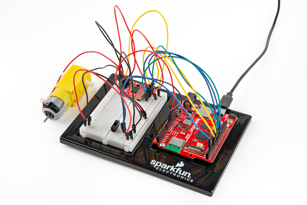
Project Overview
In this circuit you will learn the basic concepts behind motor control. Motors require a lot of current, so you can’t drive them directly from a digital pin on the RedBoard. Instead, you’ll use what is known as a motor controller or motor driver board to power and spin the motor accordingly.
Project 5 - Circuit A

New Components
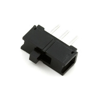
Switch
A switch is a component that controls the open-ness or closed-ness of an electric circuit. Just like the momentary buttons used in earlier circuits, a switch can only exist in one of two states: open or closed. However, a switch is different in that it will stay in the position it was last in until it is switched again.
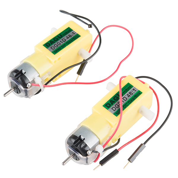
DC Gearmotors
The motors in your Inventor’s Kit have two main parts: a small DC motor that spins quickly and a plastic gearbox that gears down that output from the hobby motor so that it is slower but stronger, allowing it to move your robot. The motors have a clever design so that you can attach things that you want to spin fast (like a small fan or flag) to the hobby motor, and things that you want to be strong (like a wheel) to the plastic axle sticking out the side of the motor. The included wheels just so happen to fit on the plastic axles.

Inside the hobby motor are coils of wire that generate magnetic fields when electricity flows through them. When power is supplied to these electromagnets, they spin the drive shaft of the motor.
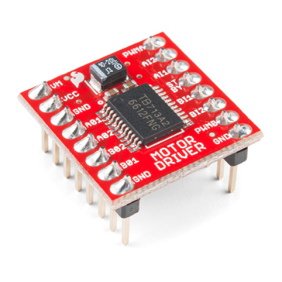
TB6612FNG Motor Driver
If you switch the direction of current through a motor by swapping the positive and negative leads, the motor will spin in the opposite direction. Motor controllers contain a set of switches (called an H-bridge) that let you easily control the direction of one or more motors. The TB6612FNG Motor Driver takes commands for each motor over three wires (two wires control direction, and one controls speed), then uses these signals to control the current through two wires attached to your motor.
New Concepts
Integrated Circuits (ICs) and Breakout Boards
An Integrated Circuit (IC) is a collection of electronic components — resistors, transistors, capacitors, etc. — all stuffed into a tiny chip and connected together to achieve a common goal. They come in all sorts of flavors, shapes, and sizes. The chip that powers the RedBoard, the RP2350, is an IC. The chip on the motor driver, the TB6612FNG, is another IC, one designed to control motors, referred to as an H-bridge.
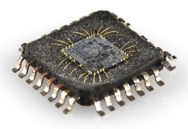
The guts of an integrated circuit, visible after removing the top.
Integrated circuits are often too small to work with by hand. To make working with ICs easier and to make them breadboard-compatible, they are often added to a breakout board, which is a printed circuit board that connects all the IC’s tiny legs to larger ones that fit in a breadboard. The motor driver board in your kit is an example of a breakout board.
Hookup Guide
Most ICs have polarity and usually have a polarity marking in one of the corners. The motor driver is no exception. Be sure to insert the motor driver as indicated in the circuit diagrams. The motor driver pins are shown in the image below.
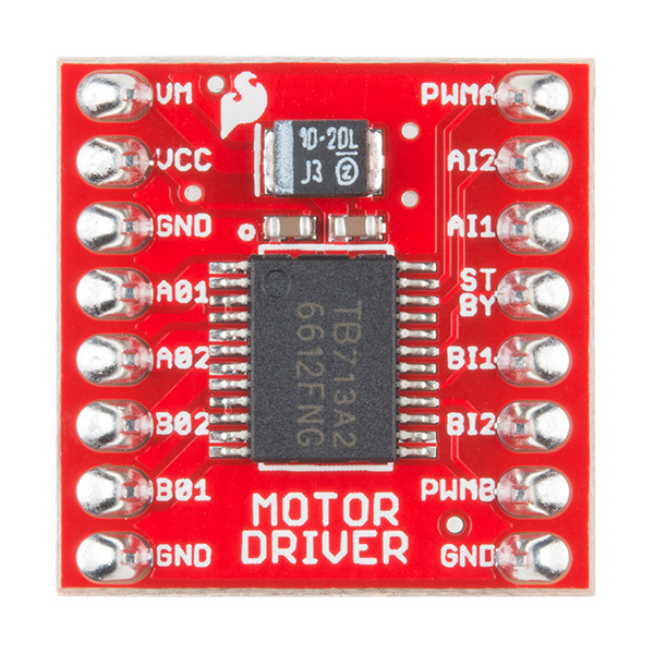
Each pin of the motor driver and its function is covered in the table below.
| Pin Label | Function | Power/Input/Output | Notes |
|---|---|---|---|
| VM | Motor Voltage | Power | This is where you provide power for the motors (2.2V to 13.5V) |
| VCC | Logic Voltage | Power | This is the voltage to power the chip and talk to the microcontroller (2.7V to 5.5V) |
| GND | Ground | Power | Common Ground for both motor voltage and logic voltage (all GND pins are connected) |
| STBY | Standby | Input | Allows the H-bridges to work when high (has a pulldown resistor so it must actively be pulled high) |
| AIN1/BIN1 | Input 1 for channels A/B | Input | One of the two inputs that determines the direction |
| AIN2/BIN2 | Input 2 for channels A/B | Input | One of the two inputs that determines the direction |
| PWMA/PWMB | PWM input for channels A/B | Input | PWM input that controls the speed |
| A01/B01 | Output 1 for channels A/B | Output | One of the two outputs to connect the motor |
| A02/B02 | Output 2 for channels A/B | Output | One of the two outputs to connect the motor |
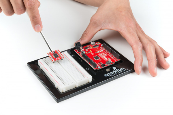
When you’re finished with Project 5, removing the motor driver from the breadboard can be difficult due to its numerous legs. To make this easier, use the included screwdriver as a lever to gently pry it out. Be careful not to bend the legs as you remove it.
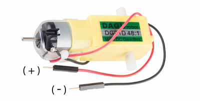
The motors are also polarized. However, motors are unique in that they will still work when the two connections are reversed. They will just spin in the opposite direction when hooked up backward. To keep things simple, always think of the red wire as positive ( + ) and the black wire as negative ( - ).
Last, the switch is not polarized. It works the same no matter its orientation.
READY TO START HOOKING EVERYTHING UP? Check out the circuit diagram and hookup table below to see how everything is connected.
Circuit Diagram
Note for Advanced Users: If you know how to read datasheets and schematics, you can also refer to the schematic below as an alternative.
Hookup Table
Programming the RedBoard
The SparkFun RedBoard IoT is programmed using MicroPython and this project uses MicroPython commands to control the circuit. Before this is possible, a MicroPython tool is needed to communicate with the RedBoard.
Selecting a MicroPython Tool
Our suggested tool is the Thonny IDE. For instructions on how to install and use Thonny, check out our Thonny Guide.
The first step to enter commands on the RedBoard is to select a tool that allows direct interaction with MicroPython.
While a variety of methods exist to communicate with the RedBoard, the following tools are the most popular: Thonny, PyCharm and the command mpremote.
Once you select and install a tool, make sure your RedBoard is connected to your computer, and the micropython tool is connected to the RedBoard. Once connected, you should have access to the MicroPython REPL command line.
Remember that the source files for each SIK circuit are already on your IoT RedBoard RP2350 in the “sik_examples” folder. So if using the suggested Thonny tool, you can select the example for this circuit and run it directly with the green “run current script” button rather than executing lines individually.
Entering MicroPython Commands
Step 1 - Setup
Lets start by importing any of the libaries we plan on using and setting up our pins.
from machine import Pin # Allows us to use "Pin" to use code to interface with the pins on our board
from machine import PWM # Allows us to use "PWM" (pulse-width modulation) to control the speed of our motors

# Motor A control pins
motorAIN1 = Pin(31, Pin.OUT) # Control pin for motor A input 1
motorAIN2 = Pin(32, Pin.OUT) # Control pin for motor A input 2

motorAPWM =  PWM(Pin(33), freq=490, duty_u16=0) # PWM pin for motor A with frequency of 1000 Hz and initial duty cycle (on time) of 0

# Motor B control pins (commenting out until next circuit)
# motorBIN1 = Pin(21, Pin.OUT) # Control pin for motor B input 1
# motorBIN2 = Pin(35, Pin.OUT) # Control pin for motor B input 2
# motorBPWM = PWM(Pin(34), freq=1000, duty_u16=0) # PWM pin for motor B with frequency of 1000 Hz and initial duty cycle (on time) of 0

# Switch pin
switchPin = Pin(28, Pin.IN, Pin.PULL_UP)  # Switch pin with pull-up resistor
Step 2 - Setting Up Motor Spin Function
Now let’s create a function where we spin the motor at a given speed. Note how we can use the two input pins to change the direction of the motor and the PWM pin to change the speed of the motor.
# Function to set motor A direction and speed
# Speed can be a positive or negative integer in the range of -65535 to 65535
# Positive values spin the motor forward, negative values spin it backward, and zero stops the motor.
def spin_motor(speed):
    if speed > 0:  # If speed is positive, spin forward
        motorAIN1.value(1)  # Set motor A input 1 high
        motorAIN2.value(0)  # Set motor A input 2 low
    elif speed < 0:  # If speed is negative, spin backward
        motorAIN1.value(0)  # Set motor A input 1 low
        motorAIN2.value(1)  # Set motor A input 2 high
    else:  # If speed is zero, stop the motor
        motorAIN1.value(0)
        motorAIN2.value(0)

    # We've already taken care of the negative or positive speed by setting the direction of the motor
    # Now we just need to set the PWM duty cycle based on the absolute value of speed
    speed = abs(speed)  # Use the absolute value of speed for PWM duty cycle

    # In functions where we allow users to pass their own arguments (in this case speed),
    # we need to make sure that what they have set is within the allowed range for
    # our hardware otherwise unexpected things might happen. In our case, PWM duty cycle must be
    # between 0 and 65535 so we'll check that here and make sure it is within that range:
    if speed > 65535:
        print("Speed exceeds maximum limit, setting to maximum allowed speed.")
        speed = 65535

    motorAPWM.duty_u16(speed)  # Set the PWM duty cycle to the absolute value of speed
Step 3 - Spinning the Motor
Finally, let’s use our function to run the motor at the set speed when the switch is flipped to the ON position and stop it when the switch is in the OFF position.
# Feel free to change this speed value to test running the motor at different speeds!
speed = 30000  # Example speed value to test the motor (should be between -65535 and 65535)

# infinite loop to keep the program running
while True:
    if switchPin.value() == 0:  # Check if the switch is pressed (active low)
        spin_motor(speed)  # Spin the motor at the specified speed
    else:
        spin_motor(0)  # Stop the motor if the switch is not pressed
What You Should See
When you flip the switch, the motor will turn on and spin at the speed set by the motor speed variable. Set the speed to the number 0 to stop the motor. Adding a piece of tape to the motor shaft makes it easier to see it spinning.
Coding Challenges
| Challenge | Description |
|---|---|
| Make the switch change directions | Change the code so that the position of the switch changes the direction of the motor instead of turning it on and off. |
| Replace the switch with a button | Try wiring a button into the circuit instead of the sliding switch. Now the motor only turns on when you push the button. |
| Replace the switch with a sensor | Try changing the code so that the motor is activated by another sensor, like the photoresistor. |
Troubleshooting
| Problem | Solution |
|---|---|
| Motor not spinning | Check the wiring to the motor driver. There are a lot of connections, and it’s easy to mix one of them up with another. If it is still not working, you can test the B channel by moving your motor. You’ll need to change the code as well. |
| Switch not working | Make sure that you are hooked up to the middle pin and one side pin on the switch. |
| Still not working? | Jumper wires unfortunately can go "bad" from getting bent too much. The copper wire inside can break, leaving an open connection in your circuit. If you are certain that your circuit is wired correctly and that your code is error-free and uploaded but you are still encountering issues, try replacing one or more of the jumper wires for the component that is not working. |
You’ve Completed Circuit 5A!
Continue to circuit 5B to get both motors going in an RC Robot!