
Project Overview
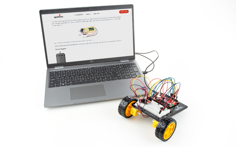
It’s remote control time! In this circuit, you’ll use a motor driver to control the speed and direction of two motors. You will also learn how to read multiple pieces of information from a string list so that you can use it to tell the robot what direction to move in and how far to move.
Project 5 - Circuit B

New Concepts
ASCII Characters
ASCII is a standard formalized in the 1960s that assigns numbers to characters. This is a method of character encoding. When typing on a computer keyboard, each character you type has a number associated with it. This is what allows computers to know whether you are typing a lowercase “a,” an uppercase “A” or a random character such as ampersand (&). In this experiment, you will be sending characters with a MicroPython function to move your remote control robot. When you send a character, the microcontroller is actually interpreting that as a specific number. There are tons of ASCII tables available online. These tables make it easier to know which character is represented by which number.
Converting Strings to Integers
String variables hold words like “dog” or “Robert Smith” that are made up of multiple characters. Python has a set of special built-in methods for converting between different types of variable such as strings and integers. To convert an integer to a string you can use the str() method and to convert from a string to an integer you can use the int() method. You can see the type of a variable with the type() method.
>>> myVariable = 5
>>> type(myVariable)
<class 'int'>
>>> myString = str(myVariable)
>>> type(myString)
<class 'str'>
>>> myInteger = int(myString)
>>> type(myInteger)
<class 'int'>
Hardware Hookup
Before you build this circuit, you’ll need to make a few modifications to the breadboard baseplate to make it more robot-like!
Assembling the Robot
Using scissors, cut two strips of Dual Lock that are 1.25 inches (3.175cm) long and 1 inch (2.5cm) wide. Remove the adhesive backing, and attach the two pieces to the very corners of the baseplate on the side located under the breadboard.
Note: You will likely have a piece of Dual Lock in the center of your baseplate from Project 4. Leave it if so. It will be used in the next circuit.
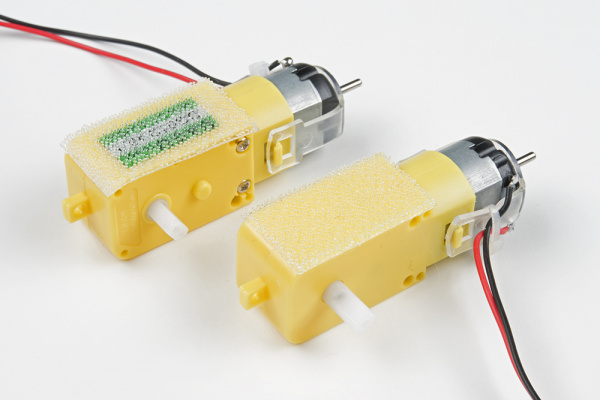
Cut two more strips that are 1.25 inches (3.175cm) long and 3/4 inch (1.9cm) wide. Remove the adhesive backing, and attach the strips to the two motors. Be sure that your motors are mirror images of each other when you attach the Dual Lock.
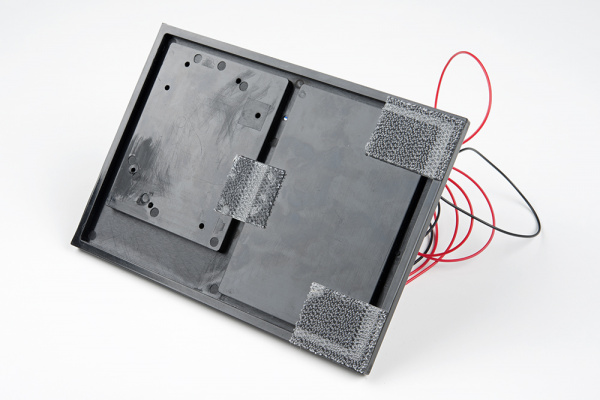
Press the motors to the baseplate, connecting the two Dual Lock surfaces. Try to get the motors as straight as possible so your robot will drive straight.
The bottom of your baseplate should look like the image below. Remember that the two motors should be mirror images of each other.
Note: The direction in which the motor wires face is arbitrary. Having them face out makes the circuit easier to build. Having them face in makes the circuit more robust against wires getting ripped out.
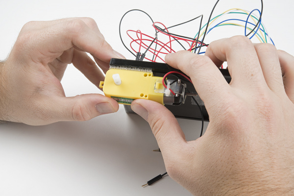
Attach the wheels by sliding them onto the plastic shafts on the gearmotor. The shaft is flat on one side, as is the wheel coupler. Align the two, and then press to fit the wheel onto the shaft.
Last, clip the binder clip onto the back end of the robot. This will act as a caster as the robot drives around.
Once you’re finished, it’s time to build the circuit. You may choose to remove the motors or leave them on while you build the circuit.
READY TO START HOOKING EVERYTHING UP? Check out the circuit diagram and hookup table below to see how everything is connected.
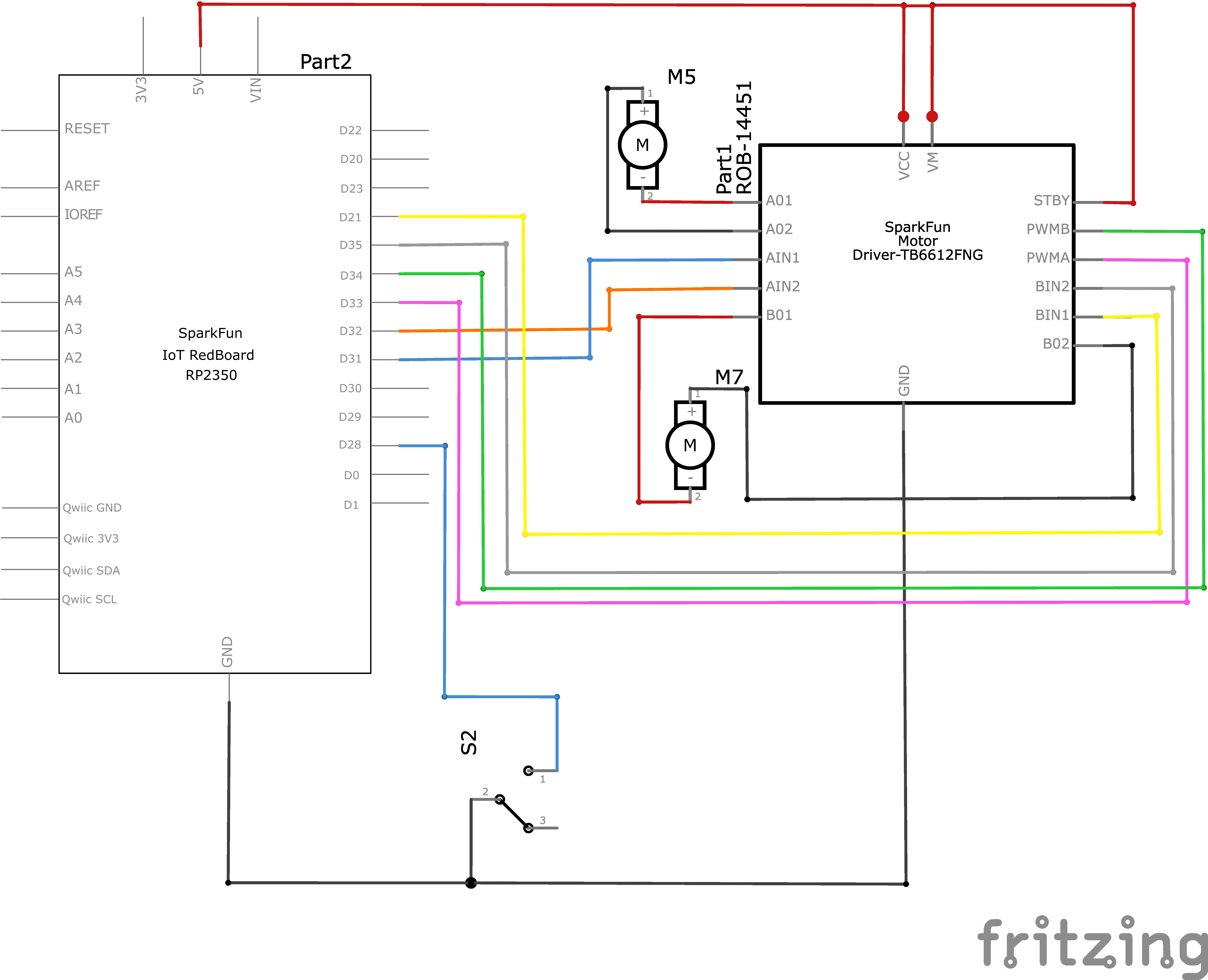
Circuit Diagram
Note for Advanced Users: If you know how to read datasheets and schematics, you can also refer to the schematic below as an alternative.
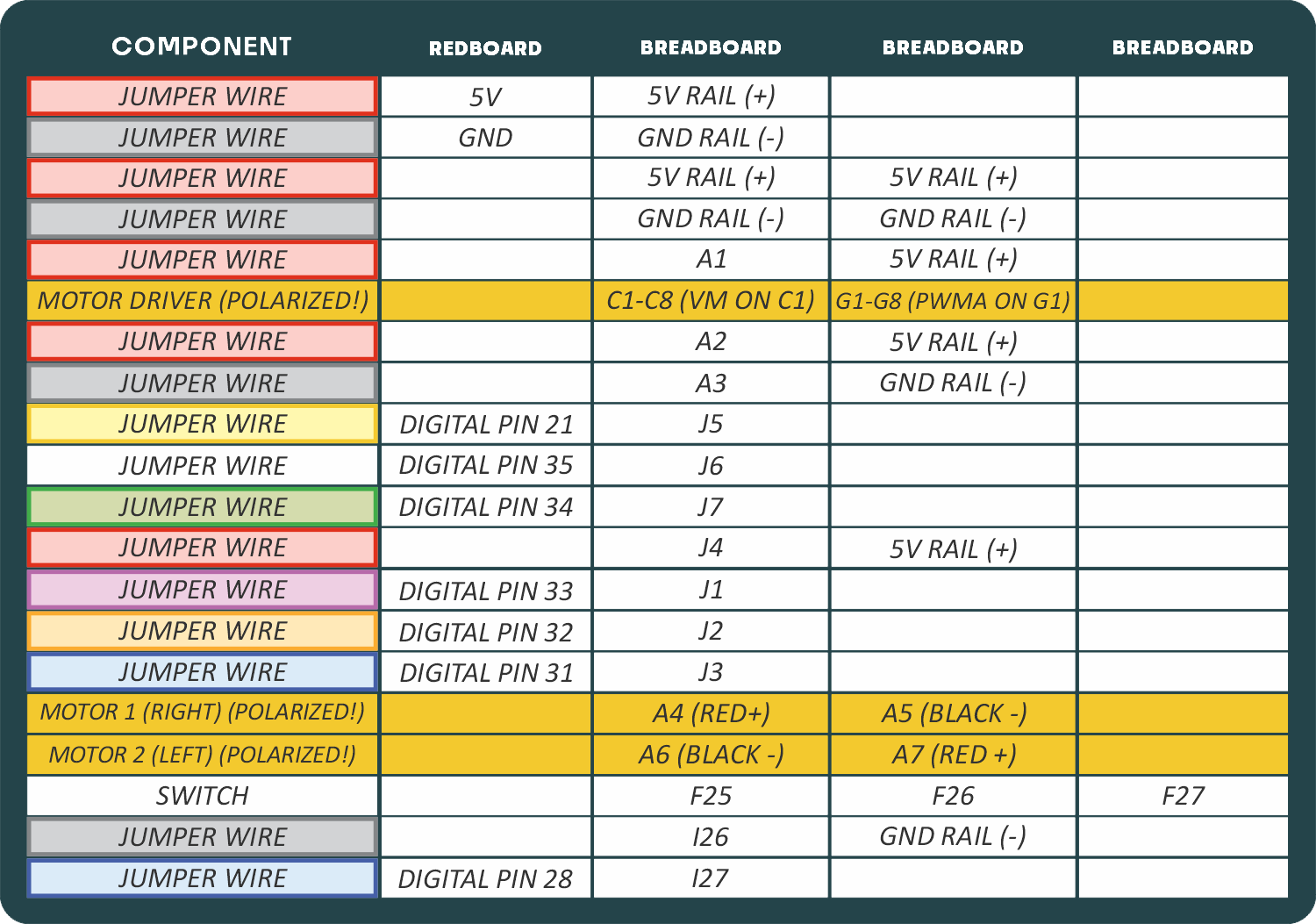
Hookup Table
Programming the RedBoard
The SparkFun RedBoard IoT is programmed using MicroPython and this project uses MicroPython commands to control the circuit. Before this is possible, a MicroPython tool is needed to communicate with the RedBoard.
Selecting a MicroPython Tool
Our suggested tool is the Thonny IDE. For instructions on how to install and use Thonny, check out our Thonny Guide.
The first step to enter commands on the RedBoard is to select a tool that allows direct interaction with MicroPython.
While a variety of methods exist to communicate with the RedBoard, the following tools are the most popular: Thonny, PyCharm and the command mpremote.
Once you select and install a tool, make sure your RedBoard is connected to your computer, and the micropython tool is connected to the RedBoard. Once connected, you should have access to the MicroPython REPL command line.
Remember that the source files for each SIK circuit are already on your IoT RedBoard RP2350 in the “sik_examples” folder. So if using the suggested Thonny tool, you can select the example for this circuit and run it directly with the green “run current script” button rather than executing lines individually.
Entering MicroPython Commands
Step 1 - Setup
Lets start by importing any of the libaries we plan on using and setting up our pins.
from machine import Pin # Allows us to use "Pin" to use code to interface with the pins on our board
from machine import PWM # Allows us to use "PWM" (pulse-width modulation) to control the speed of our motors

# Motor A control pins
motorAIN1 = Pin(31, Pin.OUT) # Control pin for motor A input 1
motorAIN2 = Pin(32, Pin.OUT) # Control pin for motor A input 2

motorAPWM =  PWM(Pin(33), freq=500, duty_u16=0) # PWM pin for motor A with frequency of 490 Hz and initial duty cycle (on time) of 0

# Motor B control pins (commenting out until next circuit)
motorBIN1 = Pin(21, Pin.OUT) # Control pin for motor B input 1
motorBIN2 = Pin(35, Pin.OUT) # Control pin for motor B input 2
motorBPWM = PWM(Pin(34), freq=500, duty_u16=0) # PWM pin for motor B with frequency of 490 Hz and initial duty cycle (on time) of 0

# Switch pin
switchPin = Pin(28, Pin.IN, Pin.PULL_UP)  # Switch pin with pull-up resistor
Step 2 - Constants
Now lets make some constant values to tune our robot’s motion. Once your robot is running you can tweak these values to make the distance travelled by the robot more accurate.
# This is the number of milliseconds that it takes the robot to drive 1 inch
# it is set so that if you tell the robot to drive forward 25 units, the robot drives about 25 inches
driveTime = 125

# this is the number of milliseconds that it takes to turn the robot 1 degree
# it is set so that if you tell the robot to turn right 90 units, the robot turns about 90 degrees
turnTime = 10

# Note: these numbers will vary a little bit based on how you mount your motors, the friction of the
# surface that your driving on, and fluctuations in the power to the motors.
# You can change the driveTime and turnTime to make them more accurate
Step 3 - Spinning the Motors
Now let’s create a function where we spin the motors at a given speed. Note how we can use the two input pins to change the direction of the motors and the PWM pins to change the speed of the motors. Notice how the first function right_motor is the same as our spin_motor function from Circuit 5A. We’ve also added a similar function for spinning the left motor.
# Function to set motor A direction and speed
# Speed can be a positive or negative integer in the range of -65535 to 65535
# Positive values spin the motor forward, negative values spin it backward, and zero stops the motor.
def spin_right_motor(speed):
    if speed > 0:  # If speed is positive, spin forward
        motorAIN1.value(1)  # Set motor A input 1 high
        motorAIN2.value(0)  # Set motor A input 2 low
    elif speed < 0:  # If speed is negative, spin backward
        motorAIN1.value(0)  # Set motor A input 1 low
        motorAIN2.value(1)  # Set motor A input 2 high
    else:  # If speed is zero, stop the motor
        motorAIN1.value(0)
        motorAIN2.value(0)

    # We've already taken care of the negative or positive speed by setting the direction of the motor
    # Now we just need to set the PWM duty cycle based on the absolute value of speed
    speed = abs(speed)  # Use the absolute value of speed for PWM duty cycle

    # In functions where we allow users to pass their own arguments (in this case speed),
    # we need to make sure that what they have set is within the allowed range for
    # our hardware otherwise unexpected things might happen. In our case, PWM duty cycle must be
    # between 0 and 65535 so we'll check that here and make sure it is within that range:
    if speed > 65535:
        print("Speed exceeds maximum limit, setting to maximum allowed speed.")
        speed = 65535

    motorAPWM.duty_u16(speed)  # Set the PWM duty cycle to the absolute value of speed

# Function to set motor B direction and speed
def spin_left_motor(speed):
    if speed > 0:  # If speed is positive, spin forward
        motorBIN1.value(1)  # Set motor B input 1 high
        motorBIN2.value(0)  # Set motor B input 2 low
    elif speed < 0:  # If speed is negative, spin backward
        motorBIN1.value(0)  # Set motor B input 1 low
        motorBIN2.value(1)  # Set motor B input 2 high
    else:  # If speed is zero, stop the motor
        motorBIN1.value(0)
        motorBIN2.value(0)

    speed = abs(speed)  # Use the absolute value of speed for PWM duty cycle

    if speed > 65535:
        print("Speed exceeds maximum limit, setting to maximum allowed speed.")
        speed = 65535

    motorBPWM.duty_u16(speed)  # Set the PWM duty cycle to the absolute value of speed
Step 4 - Direction Functions
Now let’s make some functions for moving forward, backward, right, and left.
from time import sleep # Import sleep function to add delays

# Feel free to change this speed value to test running the motor at different speeds!
speed = 30000  # Example speed value to test the motor (should be between -65535 and 65535)
turnCalibration = 0 # Calibration value for tuning how much faster we drive one motor than the other when turning

def forward(distance):
    spin_right_motor(speed)  # Spin right motor forward
    spin_left_motor(speed)   # Spin left motor forward
    sleep(driveTime * 0.001 * distance)
    spin_right_motor(0)  # Stop right motor
    spin_left_motor(0)   # Stop left motor

def backward(distance):
    spin_right_motor(-speed)  # Spin right motor backward
    spin_left_motor(-speed)   # Spin left motor backward
    sleep(driveTime * 0.001 * distance)
    spin_right_motor(0)  # Stop right motor
    spin_left_motor(0)   # Stop left motor

def right(distance):
    spin_right_motor(speed + turnCalibration)  # Spin right motor forward with calibration
    spin_left_motor(-speed)  # Spin left motor backward
    sleep(turnTime * 0.001 * distance)
    spin_right_motor(0)  # Stop right motor
    spin_left_motor(0)   # Stop left motor

def left(distance):
    spin_right_motor(-speed)  # Spin right motor backward
    spin_left_motor(speed + turnCalibration)  # Spin left motor forward with calibration
    sleep(turnTime * 0.001 * distance)
    spin_right_motor(0)  # Stop right motor
    spin_left_motor(0)   # Stop left motor
Step 5 - Drive From a String
Now, let’s make a function that allows us to easily “remote control” our robot. Our function will accept strings of the form "direction distance" to drive for a specified distance in a specified direction. For example, we can supply r 5 to drive right for 5 distance units. Let’s allow users of our function to enter the following directions:
- Forward: ‘f’ or ‘F’
- Backward: ‘b’ or ‘B’
- right: ‘r’ or ‘R’
- left: ‘l’ or ‘L’
def drive(inputString):
    # Breaking up a string into usable parts is called "parsing"
    # We can use the split function to break up a string into a list of words
    inputList = inputString.split()  # Split the input string into a list of words
    # the first word is the direction and the second is the distance
    if len(inputList) < 2:  # Check if there are at least two words in the input
        print("Invalid input. Please provide a direction and a distance.")
        return

    direction = inputList[0].lower()  # Get the first word and convert it to lowercase (so we can accept 'f' or 'F')
    distance = int(inputList[1])  # Get the second word and convert it to an integer

    # check the switch state and only drive if the switch is pressed
    if switchPin.value() == 1:  # If the switch is in OFF position
        print("Switch is in the OFF position. Cannot drive.")
        return # Notice how we can use "return" to exit the function early if we don't want to do anything

    # Go in the direction specified by the user by using our motor functions
    if direction == 'f':
        forward(distance)
    elif direction == 'b':
        backward(distance)
    elif direction == 'r':
        right(distance)
    elif direction == 'l':
        left(distance)
    else:
        print("Invalid direction. Please use 'f' for forward, 'b' for backward, 'r' for right, or 'l' for left.")
Step 6 - Drive!
Finally, let’s play with using our movement function! Feel free to play with entering movement directives one at a time, or try creating a list of multiple actions and running them all in order.
Here’s an example of how we could drive with a single command:
# Single test of the drive function:
drive("f 10")  # Example test to drive forward 10 units
# You can call the drive function with different inputs to test the robot's movement
Here’s an example of how we could drive with multiple commands in a for loop:
# Test of delivering multiple commands to the robot in a "for" loop:
commands = [
    "f 5",  # Drive forward 5 units
    "r 90",  # Turn right 90 units
    "b 3",  # Drive backward 3 units
    "l 45",  # Turn left 45 units
    "f 10"   # Drive forward 10 units
]

for c in commands:
    print("Executing command:", c)
    drive(c)  # Execute each command in the list
    sleep(1)  # Add a delay between commands to see what's happening more clearly

# TIP: If you want the robot running these commands until you stop it manually, put the for loop inside a while loop like below:
# while True:
#     for c in commands:
#         print("Executing command:", c)
#         drive(c)  # Execute each command in the list
#         sleep(1)  # Add a delay between commands to see what's happening more clearly
What You Should See
When you run the drive() command in a cell, the robot should drive with the distance and direction specified. When you execute the ‘for’ loop with multiple commands, the robot should execute the commands in order with a small delay between each
Code Challenges
| Challenge | Description |
|---|---|
| Replace the switch with a button | Try wiring a button into the circuit instead of the sliding switch. Now the motor only turns on when you push the button! |
| Replace the switch with a sensor | Try changing the code so that the motor is activated by another sensor, like the photoresistor. |
Troubleshooting
| Problem | Solution |
|---|---|
| Motor not spinning | Check the wiring to the motor driver. There are a lot of connections, and it’s easy to mix one of them up with another. If only one motor is working, check the wires coming from the non-working motor. Make sure they have not come loose from the motor. |
| Switch not working | Make sure that you are hooked up to the middle pin and one side pin on the switch. |
| Still not working? | Jumper wires unfortunately can go "bad" from getting bent too much. The copper wire inside can break, leaving an open connection in your circuit. If you are certain that your circuit is wired correctly and that your code is error-free and uploaded but you are still encountering issues, try replacing one or more of the jumper wires for the component that is not working. |
You’ve Completed Circuit 5B!
Continue to circuit 5C to learn about distance sensors.