
Project Overview
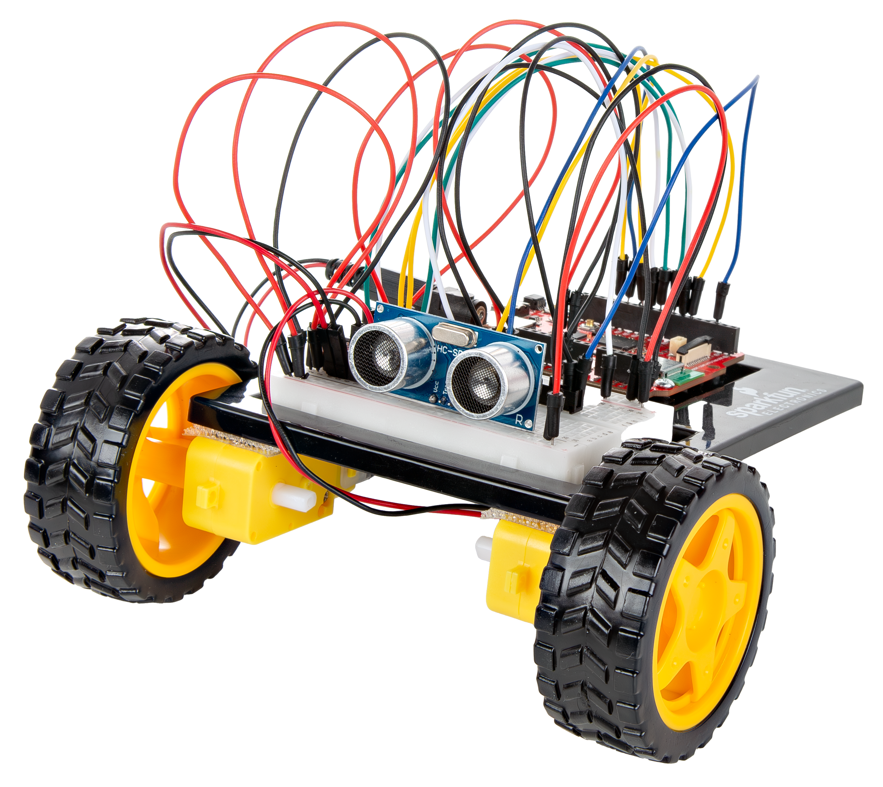
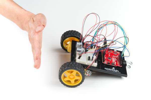
Free the robots! In this circuit, you’ll unplug your robot and program it to navigate the world on its own. When the robot senses an object using the distance sensor, it will back up and change course.
Project 5 - Circuit C

New Concepts
Autonomous Vehicles
The robot that you will build uses a simple sensor to avoid obstacles. This kind of system is used in Mars rovers, autonomous cars and the bots built for all kinds of robotics competitions. Understanding this example code will set you on the path to building bigger and better autonomous vehicles!
Hardware Hookup
Keep in mind that the ultrasonic distance sensor needs a clear path to avoid unwanted interruptions in your robot’s movements. Keep the distance sensor clear of any wires from your circuit.
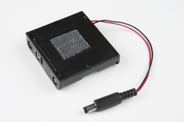
Battery Holder Attachment
It’s time to make this robot mobile by adding the battery pack.
If you did not attach the battery pack in Project 4, cut two pieces of Dual Lock that are about 1 inch x 1 inch (2.5cm x 2.5cm) each. Remove the adhesive backing and attach one piece to the back of the battery holder.
Adhere the second piece to the bottom of the baseplate, directly in the middle.
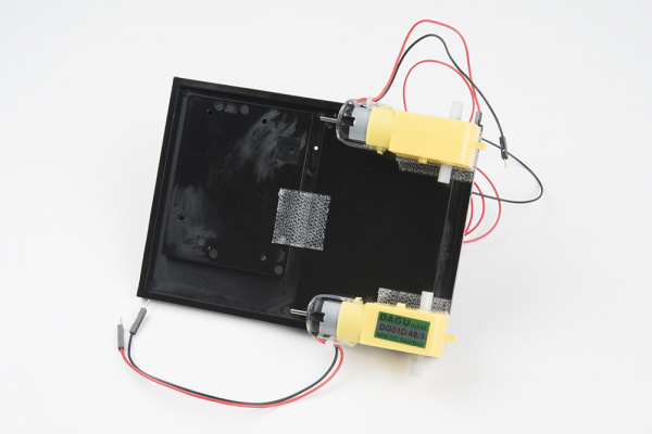
Press the battery holder to the baseplate so that the two pieces of Dual Lock snap together. Insert the batteries into the holder if you have not done so already. Remember that batteries are polarized and can only go in one way.
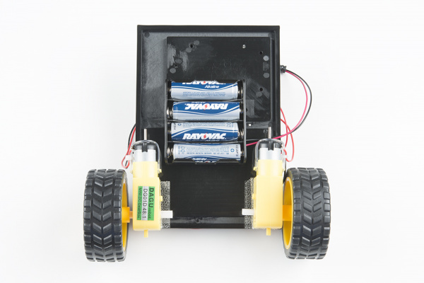
Clip the binder clip back on, and you are ready to roll!
You can choose to remove the motors and battery pack while you build the circuit or leave them on. The choice is yours.
Circuit Diagram
Note for Advanced Users: If you know how to read datasheets and schematics, you can also refer to the schematic below as an alternative.
Hookup Table
Programming the RedBoard
The SparkFun RedBoard IoT is programmed using MicroPython and this project uses MicroPython commands to control the circuit. Before this is possible, a MicroPython tool is needed to communicate with the RedBoard.
Selecting a MicroPython Tool
Our suggested tool is the Thonny IDE. For instructions on how to install and use Thonny, check out our Thonny Guide.
The first step to enter commands on the RedBoard is to select a tool that allows direct interaction with MicroPython.
While a variety of methods exist to communicate with the RedBoard, the following tools are the most popular: Thonny, PyCharm and the command mpremote.
Once you select and install a tool, make sure your RedBoard is connected to your computer, and the micropython tool is connected to the RedBoard. Once connected, you should have access to the MicroPython REPL command line.
Remember that the source files for each SIK circuit are already on your IoT RedBoard RP2350 in the “sik_examples” folder. So if using the suggested Thonny tool, you can select the example for this circuit and run it directly with the green “run current script” button rather than executing lines individually.
Entering MicroPython Commands
NOTE: This is a special circuit that we will run from the battery pack. The save_file_to_main() lines below are actually all that is needed to save the correct example to your board such that it is run automatically. We will show descriptions of the other code lines as well though in case you are curious, but note that you DO NOT need to run these on your board.
Step 1 - Setup
Lets start by importing any of the libaries we plan on using and setting up our pins.
from machine import Pin # Allows us to use "Pin" to use code to interface with the pins on our board
from machine import PWM # Allows us to use "PWM" (pulse-width modulation) to control the speed of our motors
from machine import time_pulse_us
from time import sleep # Import sleep functions to add delays
from time import sleep_us # Import sleep_us to add microsecond delays

# Motor A control pins
motorAIN1 = Pin(31, Pin.OUT) # Control pin for motor A input 1
motorAIN2 = Pin(32, Pin.OUT) # Control pin for motor A input 2
motorAPWM =  PWM(Pin(33), freq=500, duty_u16=0) # PWM pin for motor A with frequency of 490 Hz and initial duty cycle (on time) of 0

# Motor B control pins (commenting out until next circuit)
motorBIN1 = Pin(21, Pin.OUT) # Control pin for motor B input 1
motorBIN2 = Pin(35, Pin.OUT) # Control pin for motor B input 2
motorBPWM = PWM(Pin(34), freq=500, duty_u16=0) # PWM pin for motor B with frequency of 490 Hz and initial duty cycle (on time) of 0

# Switch pin
switchPin = Pin(28, Pin.IN, Pin.PULL_UP)  # Switch pin with pull-up resistor

trigPin = Pin(22, Pin.OUT) # Create a pin object for the trigger pin (pin 20) and set it as an output
echoPin = Pin(20, Pin.IN) # Create a pin object for the echo pin (pin 21) and set it as an input
Step 2 - Constants
Now lets make some constant values to tune our robot’s motion. Once your robot is running you can tweak these values to make the distance travelled by the robot more accurate.
# This is the number of milliseconds that it takes the robot to drive 1 inch
# it is set so that if you tell the robot to drive forward 25 units, the robot drives about 25 inches
driveTime = 125

# this is the number of milliseconds that it takes to turn the robot 1 degree
# it is set so that if you tell the robot to turn right 90 units, the robot turns about 90 degrees
turnTime = 10

backupInches = 10 # Number of inches to back up when the robot detects an obstacle
turnDegrees = 90 # Number of degrees to turn when the robot detects an obstacle

# Note: these numbers will vary a little bit based on how you mount your motors, the friction of the
# surface that your driving on, and fluctuations in the power to the motors.
# You can change the driveTime and turnTime to make them more accurate
Step 3 - Spinning the Motors
Now let’s create a function where we spin the motors at a given speed. Note how we can use the two input pins to change the direction of the motors and the PWM pins to change the speed of the motors. Notice how the first function right_motor is the same as our spin_motor function from Circuit 5A. We’ve also added a similar function for spinning the left motor.
# Function to set motor A direction and speed
# Speed can be a positive or negative integer in the range of -65535 to 65535
# Positive values spin the motor forward, negative values spin it backward, and zero stops the motor.
def spin_right_motor(speed):
    if speed > 0:  # If speed is positive, spin forward
        motorAIN1.value(1)  # Set motor A input 1 high
        motorAIN2.value(0)  # Set motor A input 2 low
    elif speed < 0:  # If speed is negative, spin backward
        motorAIN1.value(0)  # Set motor A input 1 low
        motorAIN2.value(1)  # Set motor A input 2 high
    else:  # If speed is zero, stop the motor
        motorAIN1.value(0)
        motorAIN2.value(0)

    # We've already taken care of the negative or positive speed by setting the direction of the motor
    # Now we just need to set the PWM duty cycle based on the absolute value of speed
    speed = abs(speed)  # Use the absolute value of speed for PWM duty cycle

    # In functions where we allow users to pass their own arguments (in this case speed),
    # we need to make sure that what they have set is within the allowed range for
    # our hardware otherwise unexpected things might happen. In our case, PWM duty cycle must be
    # between 0 and 65535 so we'll check that here and make sure it is within that range:
    if speed > 65535:
        print("Speed exceeds maximum limit, setting to maximum allowed speed.")
        speed = 65535

    motorAPWM.duty_u16(speed)  # Set the PWM duty cycle to the absolute value of speed

# Function to set motor B direction and speed
def spin_left_motor(speed):
    if speed > 0:  # If speed is positive, spin forward
        motorBIN1.value(1)  # Set motor B input 1 high
        motorBIN2.value(0)  # Set motor B input 2 low
    elif speed < 0:  # If speed is negative, spin backward
        motorBIN1.value(0)  # Set motor B input 1 low
        motorBIN2.value(1)  # Set motor B input 2 high
    else:  # If speed is zero, stop the motor
        motorBIN1.value(0)
        motorBIN2.value(0)

    speed = abs(speed)  # Use the absolute value of speed for PWM duty cycle

    if speed > 65535:
        print("Speed exceeds maximum limit, setting to maximum allowed speed.")
        speed = 65535

    motorBPWM.duty_u16(speed)  # Set the PWM duty cycle to the absolute value of speed
Step 4 - Direction and Distance Functions
Now let’s make some functions for moving forward, backward, right, and left as well as for reading our distance sensor.
# Feel free to change this speed value to test running the motor at different speeds!
speed = 30000  # Example speed value to test the motor (should be between -65535 and 65535)
turnCalibration = 0 # Calibration value for tuning how much faster we drive one motor than the other when turning

def forward(distance):
    spin_right_motor(speed)  # Spin right motor forward
    spin_left_motor(speed)   # Spin left motor forward
    sleep(driveTime * 0.001 * distance)
    spin_right_motor(0)  # Stop right motor
    spin_left_motor(0)   # Stop left motor

def backward(distance):
    spin_right_motor(-speed)  # Spin right motor backward
    spin_left_motor(-speed)   # Spin left motor backward
    sleep(driveTime * 0.001 * distance)
    spin_right_motor(0)  # Stop right motor
    spin_left_motor(0)   # Stop left motor

def right(distance):
    spin_right_motor(speed + turnCalibration)  # Spin right motor forward with calibration
    spin_left_motor(-speed)  # Spin left motor backward
    sleep(turnTime * 0.001 * distance)
    spin_right_motor(0)  # Stop right motor
    spin_left_motor(0)   # Stop left motor

def left(distance):
    spin_right_motor(-speed)  # Spin right motor backward
    spin_left_motor(speed + turnCalibration)  # Spin left motor forward with calibration
    sleep(turnTime * 0.001 * distance)
    spin_right_motor(0)  # Stop right motor
    spin_left_motor(0)   # Stop left motor

def stop():
    spin_right_motor(0)  # Stop right motor
    spin_left_motor(0)   # Stop left motor

def get_distance():
    trigPin.high()
    sleep_us(10) # Send at least a 10 microsecond pulse to the trigger pin to start the measurement
    trigPin.low() # Set the trigger pin low to stop the measurement

    echoTime = time_pulse_us(echoPin, 1)

    calculatedDistance = echoTime / 148.0 #calculate the distance of the object that reflected the pulse (half the bounce time multiplied by the speed of sound)

    return calculatedDistance # Return the calculated distance
Step 5 - Autonomous Driving
Now let’s use all of the above functions to make the robot drive forward until it detects an obstacle
while True:
    # Check if the switch is pressed
    if switchPin.value() == 0:  # If the switch is pressed (active low)
        print("Switch pressed, starting robot movement...")
        spin_right_motor(speed)
        spin_left_motor(speed)
        distance = get_distance()  # Get the distance to the nearest obstacle

        if distance < 10:  # If an obstacle is detected
            print("Obstacle detected! Backing up and turning...")
            stop() # Stop for a moment
            sleep(0.200)
            backward(backupInches)  # Back up a bit
            right(turnDegrees)  # Turn right
        else:
            # print("No obstacles detected, continuing forward...")
            spin_right_motor(speed)
            spin_left_motor(speed)
    else:
        print("Switch not pressed, stopping robot movement.")
        stop()

    sleep(0.050)  # Add a small delay between measurements
What You Should See
When the switch is turned off, the robot will sit still. When the switch is turned on, the robot will drive forward until it senses an object.
When it does, it will stop, back up and turn to the right before driving forward again.
Troubleshooting Warning: HVAC systems in offices and schools have been known to interfere with the performance of the ultrasonic distance sensor. If you are experiencing sporadic behavior from your circuit, check your surroundings. If there are numerous air ducts in the room you are using, try moving to a different room that does not have ducts. The airflow from these ducts can interfere with the waves sent from the sensor, creating noise and resulting in bad readings.
Coding Challenges
| Challenge | Description |
|---|---|
| Change the distance at which your robot reacts | Try changing the distance at which your robot stops and turns away from an obstacle. |
| Change the behavior of the robot when it senses an obstacle | Try changing the code so that your robot does something different when it senses an obstacle. |
Troubleshooting
| Problem | Solution |
|---|---|
| The robot drives backward and/or turns in the wrong direction | Check the wiring of your motors and the way that they are mounted to the breadboard and baseplate. If one of your motors is flipped around, reposition it, or switch its black and red wires on the breadboard (this will reverse the direction that it turns). |
| The robot runs into obstacles | You can try gently bending the pins of the distance sensor so that it points farther up, away from the floor. The robot will get stuck if one wheel hits an object that it is driving past (the distance sensor won’t see the obstacle unless it’s in front of the robot). |
| The robot drives backward and turns when there are no obstacles | Make sure the wires are not in front of the distance sensor. Also make sure you are not in a room with large HVAC vents. As in Project 3, these vents can wreak havoc on the ultrasonic distance sensor. |
| The robot drives slow or not at all, though the RedBoard is powered | If your board is powered but the robot is slow, won't move at all, or is behaving sporadically, check the batteries. These behaviors are symptoms of low or dead batteries. |
| Still not working? | Jumper wires unfortunately can go "bad" from getting bent too much. The copper wire inside can break, leaving an open connection in your circuit. If you are certain that your circuit is wired correctly and that your code is error-free and uploaded but you are still encountering issues, try replacing one or more of the jumper wires for the component that is not working. |